


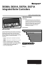

S9360A, S9361A, S9370A, S9371A INTEGRATED BOILER CONTROLLERS
69-2076—01 14
TROUBLESHOOTING
IMPORTANT
1. The following service procedures are provided
as a general guide. Follow appliance manufac-
turer’s service instructions if available.
2. On lockout and retry models, meter readings
between gas control and ignition module must
be taken within the trial for ignition period. Once
the ignition module shuts off, lockout models
must be reset through the key buttons and dis-
play. On retry models, wait for retry or reset at
the thermostat.
3. If any component does not function properly,
make sure it is correctly installed and wired
before replacing it.
4. The ignition module cannot be repaired. If it mal-
functions, it must be replaced.
5. Only trained, experienced service technicians
should service ignition systems.
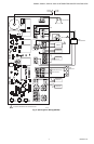
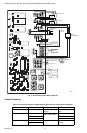
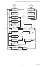
Perform the checkout as the first step in troubleshooting.
Then check the appropriate troubleshooting guide and the
schematic diagram to pinpoint the cause of the problem. If
troubleshooting indicates an ignition problem, see Ignition
System Checks below to isolate and correct the problem.
Following troubleshooting, perform the checkout
procedure again to be sure system is operating normally.
Intermittent Pilot
Ignition System Checks
STEP 1: Check ignition cable.
Make sure:
• Ignition cable does not run in contact with any metal
surfaces.
• Ignition cable is no more than 36 in. [0.9 m] long.
• Connections to the ignition module and to the igniter or
igniter-sensor are clean and tight.
• Ignition cable provides good electrical continuity.
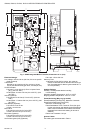
STEP 2: Check ignition system grounding. Nuisance
shutdowns are often caused by a poor or erratic ground.
• A common ground, usually supplied by the pilot burner
bracket, is required for the module and the pilot burner/
igniter sensor.
— Check for good metal-to-metal contact between
the pilot burner bracket and the main burner.
— Check the ground lead from the GND(BURNER)
terminal on the module to the pilot burner. Make
sure connections are clean and tight. If the wire is
damaged or deteriorated, replace it with No. 14-18
gauge, moisture-resistant, thermoplastic insu-
lated wire with 105° C [221° F] minimum rating.
—Check the ceramic flame rod insulator for
cracks or evidence of exposure to extreme
heat, which can permit leakage to ground.
Replace pilot burner/igniter-sensor and pro-
vide shield if necessary.
—If flame rod or bracket are bent out of position,
restore to correct position.
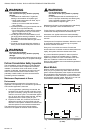
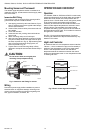
STEP 3: Check spark ignition circuit.
• Disconnect the ignition cable at the SPARK terminal on
the module.
WARNING
The ignition circuit generates over 10,000 volts
and electrical shock can result.
Energize the module and listen for the audible sparking
noise. When operating normally, there should be a
buzzing noise that turns on and off twice per second for a
duration of 1–7 seconds, depending on the model.
STEP 4: Check pilot and main burner lightoff.
• Set the system to call for heat by turning the
thermostat above room temperature.
• Watch the pilot burner during the ignition sequence.
See if:
— Ignition spark continues after the pilot is lit.
— The pilot lights and the spark stops, but main
burner does not light.
• If so, ensure adequate flame current as follows.
— Turn off furnace at circuit breaker or fuse box.
— Clean the flame rod with emery cloth.
— Make sure electrical connections are clean and
tight. Replace damaged wire with moisture-resis-
tant No. 18 wire rated for continuous duty up to
105° C [221° F].
— Check for cracked ceramic insulator, which can
cause short to ground, and replace igniter-sensor
if necessary.
— At the gas valve, disconnect main valve wire from
the MV terminal.
— Turn on power and set thermostat to call for heat.
The pilot should light but the main burner will
remain off because the main valve actuator is dis-
connected.
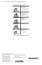
— Check the pilot flame. Make sure it is blue, steady
and envelops 3/8 to 1/2 in. [10 to 13 mm] of the
flame rod. See Fig. 11 for possible flame problems
and their causes.
— If necessary, adjust pilot flame by turning the pilot
adjustment screw on the gas control clockwise to
decrease or counterclockwise to increase pilot
flame. Following adjustment, always replace pilot
adjustment cover screw and tighten firmly to
assure proper gas control operation.
— Set temperature below room setpoint to end call
for heat.
• Recheck ignition sequence as follows.
— Reconnect main valve wire.
— Adjust thermostat above room temperature.
— Watch ignition sequence at burner.
— If spark still doesn’t stop after pilot lights, replace
module.
— If main burner doesn’t light or if main burner lights
but system locks out, check module, ground wire
and gas control as described in appropriate trou-
bleshooting chart.
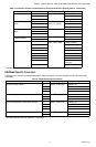
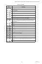
Troubleshooting Error Codes
The integrated boiler control uses advanced diagnostic
capability to assist in troubleshooting error conditions.
The following table shows the codes that could arise on
the remote or integrated display during a fault.
Suggestions are provided in Table 7 for servicing these
potential errors.