


S9360A, S9361A, S9370A, S9371A INTEGRATED BOILER CONTROLLERS
69-2076—01 2
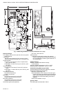
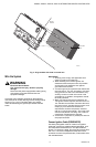
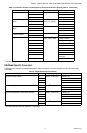
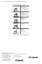
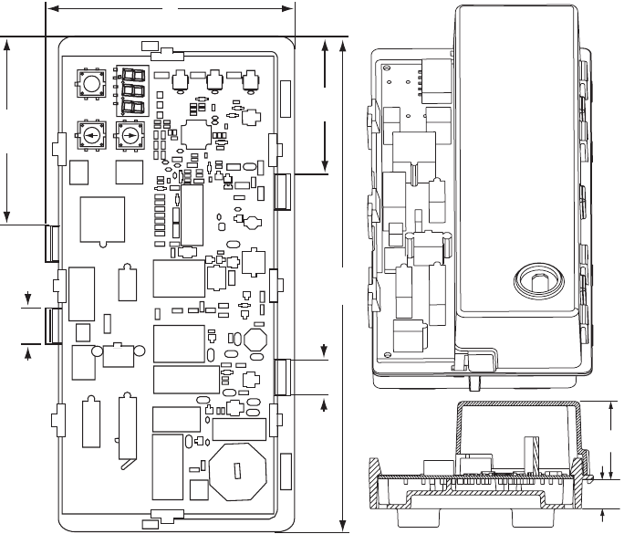
Fig. 1. S936X Integrated Boiler Controller, dimensions in in. (mm).
Electrical Ratings:
Line Voltage: 120 Vac, 60 Hz (220 Vac, 50 Hz on specific
model numbers).
Transformer:
Nominal 24 Vac (maximum 30 Vac, minimum 18 Vac).
5.0 VA plus external loads (gas valve, vent damper, etc.)
On/Off Circulator:
Full Load: 7.4A at 120 Vac (0.75 to 0.8 power factor
[PF]). (220 Vac TBD.)
Locked Rotor: 44.4A at 120 Vac (0.4 to 0.5 PF). (220
Vac TBD.)
Inducer (Optional):
Full Load: 6A at 120 Vac (0.75 to 0.8 PF). (220 Vac
TBD.)
Locked Rotor: 17.48A at 120 Vac (0.4 to 0.5 PF). (220
Vac TBD.)
Vent Damper (Optional):
Full Load: 0.5A at 24 Vac.
In Rush: 1A at 24 Vac.
Main Valve:
Full Load: 2A at 24 Vac (0.5 to 0.6 PF).
In Rush: 6A at 24 Vac (0.5 to 0.6 PF)
Pilot Valve (Optional):
Full Load: 2A at 24 Vac (0.5 to 0.6 PF)
In Rush: 6A at 24 Vac (0.5 to 0.6 PF).
Hot Surface Igniter (HSI) (Optional):
Full Load: 4.5A at 120 Vac.
Warm-up Time:
18 seconds for first trial for ignition; this varies by
model, as does the time for the second trial for igni-
tion (recommended for Norton igniter model 201 or
270 or equivalent)
Ambient Ratings:
Humidity: 0 to 95 percent relative humidity,
noncondensing.
Operating Ambient Temperature: -30°F to +150°F.
Shipping Ambient Temperature: -40°F to +175°F.
Flame Monitoring (May vary by model):
Flame Establishing Period (FEP): Maximum 2 seconds.
Flame Failure Response Time (FFRT):
Maximum: 2 seconds @ 1 µA.
Flame Stabilization Time: 4 seconds. Time from ignit-
ing the main burner and detecting loss of flame (the
flame current is allowed to be under the flame lost
threshold for this time while waiting for burner to
stabilize).
Flame Lost Threshold: 0.23 µA.
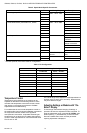
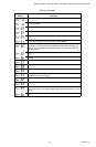
Ignition Cables:
Use cable types recommended in Table 1.
1-3/8
(35)
5/8
(16)
M24217
2 x 84.5
2 x 15
2 x 61
220.5
111
2 x 15
I