


7 68-0173—3
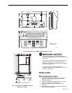
IMPORTANT
Be sure to connect the C terminal to transformer
common.
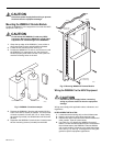
IN NEW INSTALLATION:
1. Locate the terminal strip(s) on the HVAC equipment.
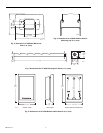
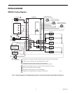
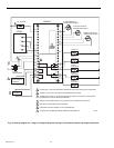
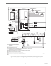
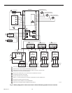
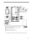
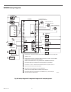
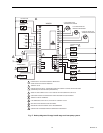
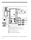
2. Refer to Fig. 11 through 20 for wiring diagrams for spe-
cific equipment applications.
3. Connect all loads to the appropriate W8900A-C wiring
terminal using 18-gauge, color-coded thermostat wire;
see Fig. 10.
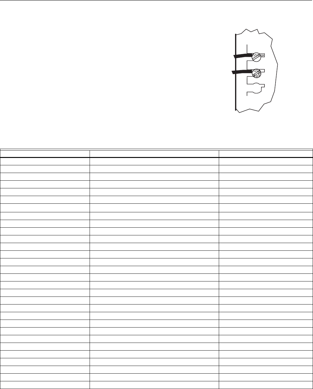
4. Use a small screwdriver to connect the loads. Do not
overtighten; device can be damaged.
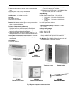
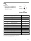
Fig. 10. Proper wiring technique for
W8900A-C and PC8900A.
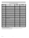
Table 2. Conventional Applications (W8900A or C).
a
PC8900A/W8900A,C are not compatible with evaporative cooling equipment.
b
In single stage heat pump applications, jumper W1 and Y1 and connect to Y. Configure the system for Auto Fan in Heat.
c
Dual fuel fan feature configured in installer setup.
d
Filter light feature available in PC8900A fan accumulation timer feature.
FOR WRAPAROUND
CONNECTION—
STRIP 7/16 IN. (11 MM)
FOR STRAIGHT
CONNECTION—
STRIP 5/16 IN. (8 MM)
M4464
W8900
W8900A, C Terminal Designation Function Existing Thermostat Designation
1 PC8900A Control Panel —
2 PC8900A Control Panel —
3 PC8900A Control Panel —
4 PC8900A Control Panel —
B Heating, changeover valve B
C 24 Vac Transformer Common C
CO
2
Carbon Dioxide Monitor —
VNT VNT Relay —
G Fan Relay G
GND Ground —
HUM Humidity Relay —
OUT Outdoor Air Temperature Sensor —
O Cooling, Changeover Valve O
R 24 Vac System Transformer R
RC 24 Vac Cooling Transformer RC
RH 24 Vac Heating Transformer RH
S, S1 Remote Air Temperature Sensor —
See note a Fan Control—Evaporative Cooling F
See note b Heat Pump Contactor P
T, T1 Discharge Air Temperature Sensor —
W1 Heating Relay W
W1 Stage 1 Heat Relay W1
W2 Stage 2 Heat Relay W2
Y1 Cooling Relay Y
Y1 Stage 1 Cool Relay Y1
Y2 Stage 2 Cool Relay Y2
See note c Fan Control (Honeywell dual fuel thermostat [T834]) 1
See note c Fan Control (Honeywell dual fuel thermostat [T834]) 2
See note d Filter Light X
none Remote Timer Contacts Z