


23 68-0173—3
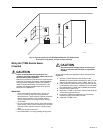
— Mount it high enough to prevent tampering or coverage
by snow, ice or debris.
• The wire distance between the C7089A and W8900A-C
should not exceed 200 ft.
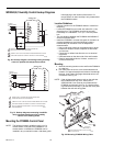
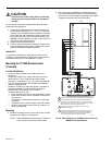
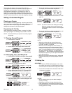
Mounting
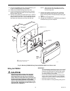
1. Remove the sensor from the mounting clip.
2. Mark the area on the surface where the C7089A mount-
ing clip will be mounted.
3. Mount the clip.
Fig. 27. Typical locations for C7089A
Outdoor Sensor.
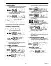
Wiring the C7089A Outdoor Sensor
(if needed)
CAUTION
Failure to use the following wiring practices can
introduce electrical interference (noise), which can
cause erratic system operation.
Keep wiring at least one foot away from large inductive
loads such as motors, line starters, lightning ballasts,
and large power distribution panels. Use shielded
cable to reduce interference when rerouting wires is
not possible. Ground the shielded cable to the ground
terminal on the W8900A-C.
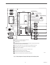
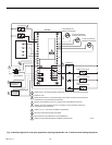
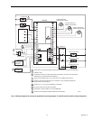
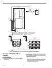
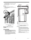
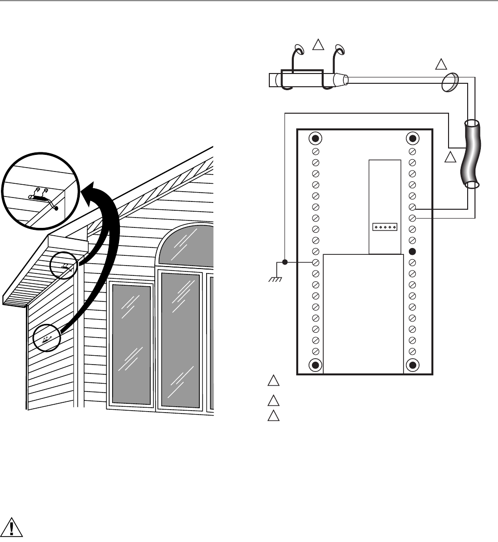
Fig. 28. Wiring diagram for C7089A Outdoor Sensor
to W8900A-C Remote Module.
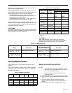
IMPORTANT
Erratic temperature readings from a sensor can
occur as a result of any of the wiring practices
described below. Use shielded cable to reduce inter-
ference if rerouting of sensor wiring is not possible.
These practices must be avoided to assure proper
operation:
— Do not route temperature sensor wiring with building
power wiring, next to control contactors or near light
dimming circuits, electric motors or welding
equipment.
— Avoid poor wiring connections.
— Avoid intermittent or missing building earth ground.
M7514
M4457
1
2
3
2
1
USE APPROPRIATE MOUNTING MEANS FOR THE TYPE
OF STRUCTURE.
PLUG WIRING HOLE WITH NONHARDENING CAULK OR PUTTY.
IF SHIELDED CABLE IS REQUIRED, GROUND TO GND TERMINAL
ON W8900.
C7089
WIRING HOLE
THROUGH
STRUCTURE
3
OUT
OUT
LED
GND
W8900