


68-0173—3 18
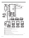
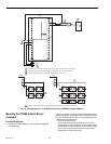
W8900A,B,C Humidity Control Hookup Diagrams
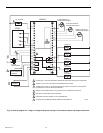
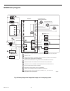
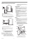
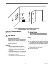
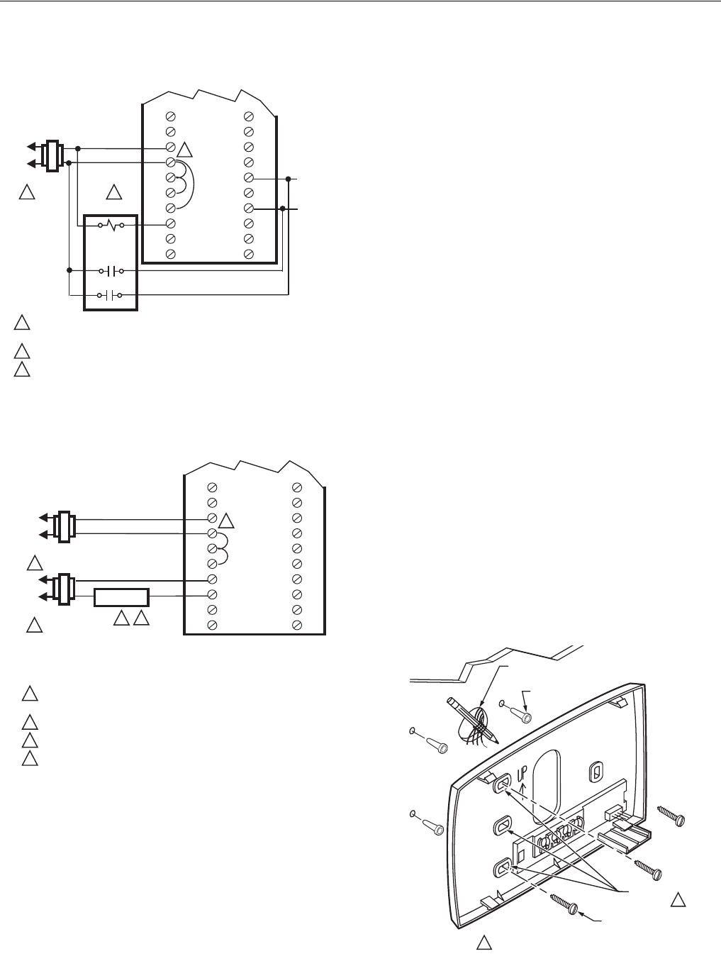
Fig. 20. Hookup diagram connecting cooling humidity
control in parallel with temperature control.
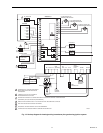
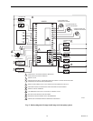
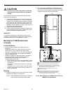
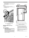
Fig. 21. Hookup diagram connecting humidifier
using separate transformers for humidity
control in the heating mode.
Mounting the PC8900A Control Panel
NOTE: The following location guidelines apply only if a
remote sensor is not part of the installation. If a
remote sensor is installed, the PC8900A can be
installed in any convenient location, with these guide-
lines applying to the location of the sensor. If a
remote sensor is used, humidity is only measured at
the PC8900A location.
Location Guidelines
• Choose a location for the PC8900A where it is safe from
tampering.
• Locate the PC8900A on an inside wall, about 5 ft (1.5m)
above the floor. The PC8900A can also be mounted
horizontally on a standard 2 x 4 in. (51 x 102 mm) outlet
box.
• The wire distance between the PC8900A and W8900A-C
should not exceed 200 ft.
• Install the PC8900A in an area with good air circulation at
average temperature. Avoid the following locations
because they can introduce errors in temperature
measurements:
— Hot or cold areas caused by concealed pipes or ducts.
— Drafts from windows, doors, fireplaces or other heat/
cool sources.
— Convection or radiant heat from the sun or electrical
equipment.
— Unheated areas on the other side of the wall location.
— Dead air areas behind doors, furniture, curtains or in
corners and alcoves.
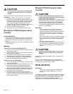
Mounting
1. Mark the mounting location on the wall for the PC8900A
or outlet box.
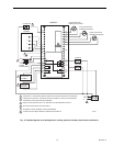
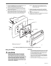
2. Run cable from the unit to a hole at the selected wall
location. Pull approximately three inches of wire through
the hole. Color-coded 18-gauge thermostat wire is rec-
ommended. See Fig. 22.
NOTE: If the old thermostat leaves marks on the wall that
the PC8900A does not cover, order part no.
205224A Wall Cover Plate to mount between the
PC8900A and the wall. See Fig. 23. Use the follow-
ing instructions and at step 7, put the wall cover plate
between the wall and wiring plate.
Fig. 22. Mounting PC8900A Wiring Plate.
L1
(HOT)
L2
1
1
2
3
3
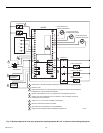
POWER SUPPLY. PROVIDE DISCONNECT MEANS AND
OVERLOAD PROTECTION AS REQUIRED.
JUMPER R TO RH TO RC FOR SINGLE TRANSFORMER APPLICATIONS.
CONFIGURE PC8900 FOR HUMIDITY CONTROL IN HEATING MODE.
M18588
2
SYSTEM
TRANSFORMER
W8900A,B,C
G
Y2
W1
W2
C
R
RH
RC
HUM
HUM
VNT
VNT
R8222N1011
1
3
4
6
Y1
FAN
COMP
L1
(HOT)
L2
1
1
2
3
4
3
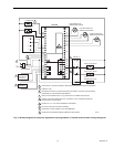
POWER SUPPLY. PROVIDE DISCONNECT MEANS AND
OVERLOAD PROTECTION AS REQUIRED.
JUMPER R TO RH TO RC FOR SINGLE TRANSFORMER APPLICATIONS.
CONFIGURE PC8900 FOR HUMIDITY CONTROL IN HEATING MODE.
USE OF A SEPARATE POWER SUPPLY TO RUN THE HUMIDIFIER
IS RECOMMENDED.
M4997
2
4
SYSTEM
TRANSFORMER
W8900A,B,C
G
Y2
Y1
W1
W2
C
R
RH
RC
HUM
HUM
VNT
VNT
HUMIDIFIER
L1
(HOT)
L2
1
WIRES
THROUGH WALL
WALL
MOUNTING
HOLES (4)
MOUNTING
SCREWS (3)
USE THREE MOUNTING HOLES THAT BEST
FIT APPLICATION
1
1
M4466
WALL
ANCHORS
(3)