


68-0173—3 26
a
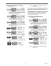
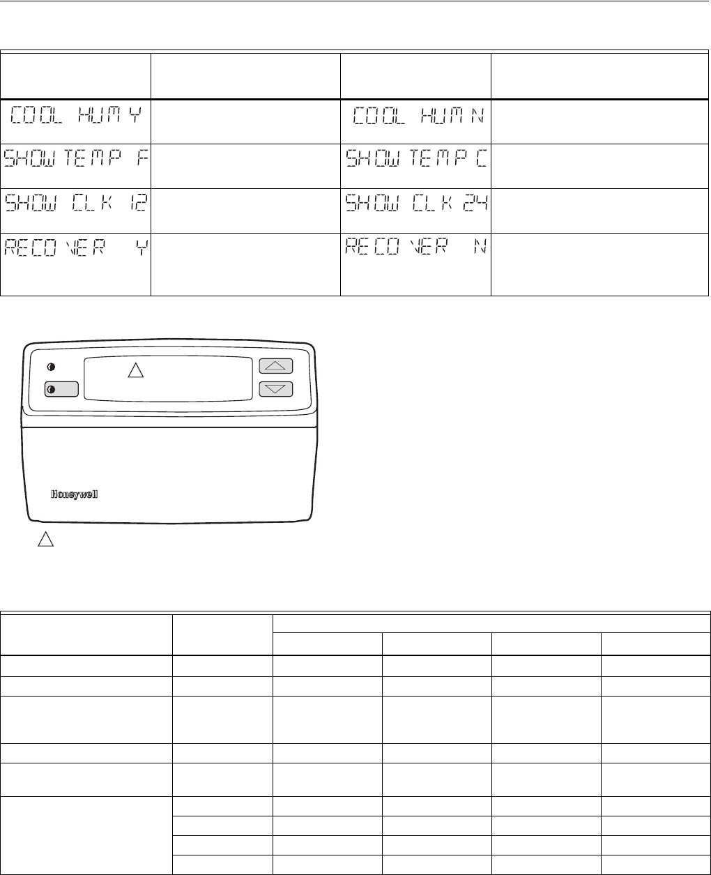
The humidity option can only be set for heat or cool. If both are set to Y, it will not honor either one.
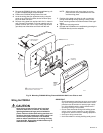
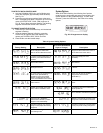
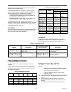
Fig. 30. Initial display for installer setup.
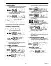
Heat Options
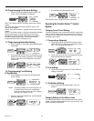
When HEAT is flashing, refer to Table 5 for the options
pertaining to the heat equipment that appear in the PC8900A
display after each press of the CHECK key. HEAT and its list
of options appear only when the system allows field selection
of cycle rates, and only stages present in the remote module
hardware are shown.
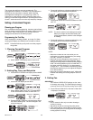
Table 5. Heating Cycle Rates.
a
When W2 is not used, configure W2 cycle rate to NC (not connected).
b
Factory setting.
c
Use these cycle rate settings if faster or slower cycling is required.
System set to control humidity in
cooling.
a
Can also have reheat
(W8900C only).
System does not control high humidity in
cooling.
PC8900A displays temperature
settings and readings in °F.
PC8900A displays temperature settings
and readings in °C.
PC8900A displays setpoint times and
clock times (12-hour clock) with AM
and PM.
PC8900A displays setpoint times and clock
times (24-hour clock) with military time.
System is set for Adaptive Intelligent
Recovery™. When recovering from
setback modes, programmed times
indicate when recovery ends. (See
Operation section for description).
System is set for conventional recovery.
When recovering from setback modes,
programmed times indicate when recovery
begins.(See Operation section for
description.)
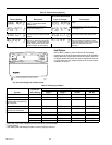
Table 4. System Setting Options
Factory-Setting Description
Other Choices (Press
Up or Down Arrowhead
Keys to Change) Description
M6371
M6386
M6372
M6387
M6373
M6388
M6374
M6389
SYSTEM
FAN
HEAT COOL
M6401
SYSTEM
CHECK
1
1
ONE OF THESE SEGMENTS WILL BE FLASHING.
System
Cycles per
Hour Setting
Display Shows
Stage 1 Stage 2
a
AUX HT EM. HT.
Gas or Oil Forced Air 6
W1 CPH 6
b
W2 CPH 6
b
AUX HT CPH 6
b
EM. HT. CPH 6
b
Electric Heat 9 W1 CPH 9 W2 CPH 9 AUX HT CPH 9 EM. HT. CPH 9
Single Stage Heat Pump,
Hydronic Heat, Condensing
Gas Furnaces
3 W1 CPH 3 W2 CPH 3 AUX HT CPH 3 EM. HT. CPH 3
Radiant Floor Heat, Gravity 1 W1 CPH 1 W2 CPH 1 AUX HT CPH 1 EM. HT. CPH 1
Cooling-only Application; no
heat sources connected
Not connected W1 CPH NC W2 CPH NC AUX HT CPH NC EM. HT. CPH NC
N/A
c
4.5 W1 CPH 4.5 W2 CPH 4.5 AUX HT CPH 4.5 EM. HT. CPH 4.5
2.5 W1 CPH 2.5 W2 CPH 2.5 AUX HT CPH 2.5 EM. HT. CPH 2.5
2 W1 CPH 2 W2 CPH 2 AUX HT CPH 2 EM. HT. CPH 2
1.5 W1 CPH 1.5 W2 CPH 1.5 AUX HT CPH 1.5 EM. HT. CPH 1.5