


39 68-0173—3
setup mode for a few seconds. After the RUN key is pressed,
the discharge air temperature is displayed when the CHECK
key is pressed (until another power outage occurs).
NOTE: When a discharge air temperature sensor is installed
and configured in an application, we recommend
interrupting the power supply briefly before leaving
the site. This removes the discharge air temperature
from the display when the CHECK key is pressed
and avoids confusion.
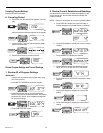
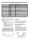
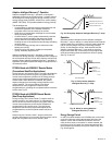
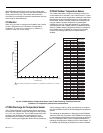
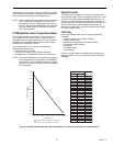
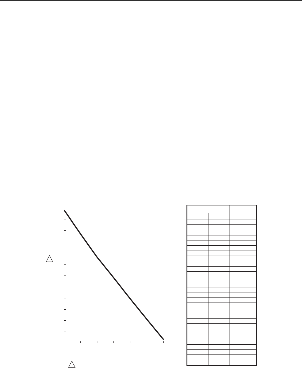
C7189A Remote Indoor Temperature Sensor
The C7189A Wall Mount Temperature Sensor provides the
input required by the Comfort Center™ control system to
sense the indoor air space temperature. See Fig. 40 for the
resistance vs. temperature characteristics for the C7189A
Remote Indoor Temperature Sensor.
At a remote location, the C7189A can also average
temperature in several ways:
• PC8900A and one C7189A.
• Four or nine C7189As in series/parallel networks.
• PC8900A and a C7189A network (four or nine sensors).
NOTE: The remote temperature (or temperature averaging
network temperature) is displayed on the PC8900A
with the Time, Day, and Mode of operation. Pressing
the CHECK key does not display the remote temper-
ature separately.
Keypad Lockout
The keypad lockout feature allows temporary settings to be
made, but the installer setup and program settings can not be
changed. This feature gives the PC8900A the security of a
locking cover with flexibility to meet the user’s schedule. To
activate keypad lockout, press and hold RUN until LOCK KEY
shows on the display (approximately three seconds). To
deactivate keypad lockout, press and hold RUN until OPEN
KEY shows on the display.
CHECK Key
Press the PC8900A CHECK key to display the following
information:
• Outdoor temperature (if C7089A installed).
• Humidity level in room.
• Discharge air temperature (if C7100A installed).
• Heating and cooling setpoints.
• Fan setting.
• Ventilation setting.
• System setting.
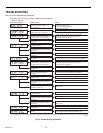
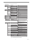
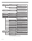
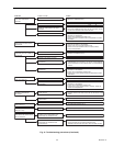
If the Check LED is lighted, troubleshooting messages are
displayed. Refer to Fig. 41 for flowchart of troubleshooting
messages.
Fig. 40. C7189A Remote Temperature Sensor resistance vs. temperature performance characteristics.
OHM RESISTANCE
F
( C )
M6357
RESISTANCE DECREASES 18.6 OHMS PER 1 F
CHANGE OR 33.4 OHMS PER 1 C CHANGE.
1
1
2000
2100
1900
1500
1600
1700
1800
1400
TEMPERATURE
40
(4)
50
(10)
60
(16)
70
(21)
80
(27)
90
(32)
100
(38)
1300
1000
1200
2200
2300
46
48
50
52
54
56
58
60
62
64
66
68
70
72
74
76
78
80
82
84
86
88
90
92
94
96
98
100
7.8
8.9
10.0
11.1
12.2
13.3
14.4
15.6
16.7
17.8
18.9
20.0
21.1
22.2
23.3
24.4
25.6
26.7
27.8
28.9
30.0
31.1
32.2
33.3
34.4
35.6
36.7
37.8
2131 to 2094
2094 to 2057
2057 to 2019
2019 to 1982
1982 to 1945
1945 to 1908
1908 to 1871
1871 to 1833
1833 to 1796
1796 to 1759
1759 to 1722
1722 to 1685
1685 to 1647
1647 to 1610
1610 to 1573
1573 to 1536
1536 to 1499
1499 to 1461
1461 to 1424
1424 to 1387
1387 to 1350
1350 to 1313
1313 to 1275
1275 to 1238
1238 to 1201
1201 to 1164
1164 to 1127
1127 to 1089
ROOM TEMPERATURE
OHMS OF
RESISTANCE
F
C