


68-0173—3 22
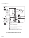
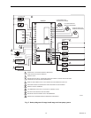
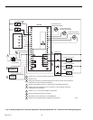
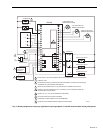
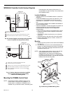
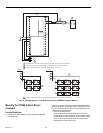
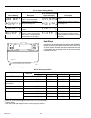
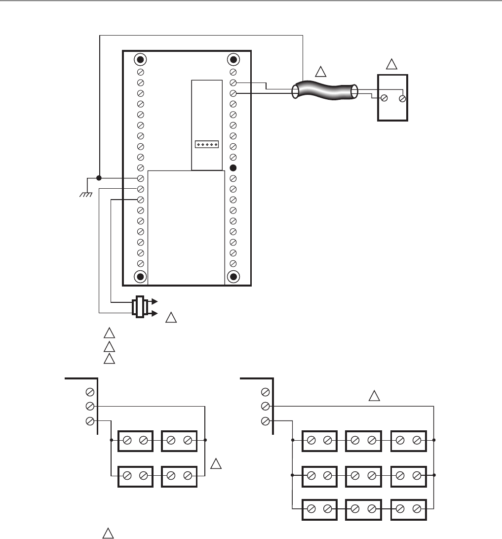
Fig. 26. Wiring diagram for C7189A Remote Sensor to W8900A-C Remote Module.
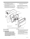
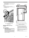
Mounting the C7089A Outdoor Sensor
(if needed)
Location Guidelines
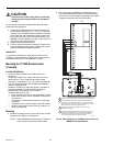
• Locate the C7089A Outdoor Sensor where it will be safe
from tampering.
• Choose an outdoor location for the sensor where there is
good air circulation at average outdoor temperature. See
Fig. 27. Locate the sensor where it can measure the true
outdoor ambient temperature:
— On a flat surface is best.
— Avoid locations that can introduce errors in sensor
measurements such as areas of direct sunlight or high
temperature, or areas where hot or cold air is blowing
out of a fan or vent such as next to the compressor
discharge line in the outdoor unit.
M4456A
W8900
C7189 C7189
W8900
C7189 C7189
C7189 C7189
C7189 C7189
C7189
C7189
C7189 C7189 C7189
4
1
2
3
2
3
4
4
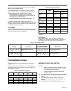
SENSORS MUST BE ARRANGED IN THIS NUMBER AND CONFIGURATION FOR PROPER OPERATION.
S1
S
LED
L1
(HOT)
L2
1
POWER SUPPLY. PROVIDE DISCONNECT MEANS AND OVERLOAD PROTECTION AS REQUIRED.
IF MORE THAN ONE C7189 REMOTE SENSOR IS REQUIRED, REFER TO DIAGRAM BELOW.
IF SHIELDED CABLE IS REQUIRED, GROUND TO GND TERMINAL ON W8900.
GND
C
R
RH
RC
C7189
W8900
S1
S
S1
S