


68-0173—3 34
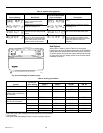
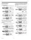
Table 10. Heat Pump System Checkout.
a
a
The polarity configuration of the reversing valve relay (O/B) determines if the O/B is always energized on first call for heat or
cool. If the reversing valve energizes with heat, then it de-energizes with cooling. Factory setting is for O/B to energize with a
call for heat.
b
O/B is energized based on installer setup or configuration.
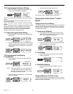
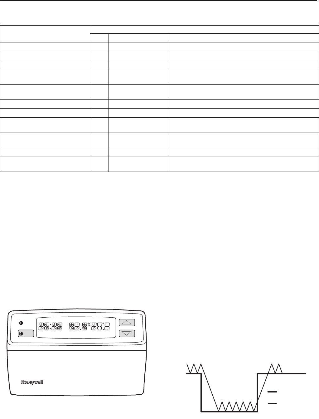
Installer Display of all Segments and Product Codes
(Optional)
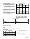
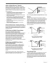
1. Press and hold CHECK key until all segments of the dis-
play are lighted. See Fig. 31.
2. Press the CHECK key four more times to view each of
the following items:
— Order specification number of the Comfort Center™
control system.
— Manufacturing date code and software revision
numbers of the Comfort Center™ control system.
— Order specification number of the remote module.
— Manufacturing date code and software revision
numbers of the remote module.
3. Press the CHECK key to return to normal operation.
Fig. 31. All segments on display.
OPERATION
The PC8900A, C7089A, C7189A, C7100A and CO
2
monitor
sense the temperature, humidity and CO
2
conditions in the
living space. This information is then transferred to the
W8900A-C Remote Module, which activates the proper
equipment based on the programmed settings.
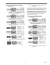
Conventional vs. Adaptive Intelligent
Recovery™ Operation
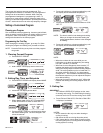
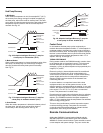
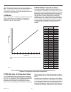
Conventional Recovery
Conventional temperature recovery starts the heating or
cooling system at the programmed set time. See Fig. 32.
Using conventional recovery requires setting the program
period times earlier than the area is occupied so the area will
be comfortable. The program may need to be adjusted
periodically to accommodate for weather and seasonal
changes. The conventional recovery method is used when
Adaptive Intelligent Recovery™ operation is disabled.
Fig. 32. Conventional recovery ramp.
Step
Result
LED Terminals Energized Equipment Operation
Remove jumper from T terminal. Off G Fan relay is energized.
Reconnect jumper to T terminal. On
G, W1/Y1, O/B
b
Fan and first-stage heat are energized.
Remove jumper from T terminal. Off
G, W1/Y1, W2, O/B
b
Fan, first- and second-stage heat are energized.
Reconnect jumper to T terminal. On G, W1/Y1, W2, AUX,
O/B
b
Fan, first-, second- and auxiliary-stage heat are energized.
Remove jumper from T terminal. Off
G, E, O/B
b
First- and second-stage heat are de-energized. Fan and
emergency heat are energized.
Reconnect jumper to T terminal. On
G, W1/Y1, O/B
b
Fan and first-stage cooling are energized.
Remove jumper from T terminal. Off
G, W1/Y1, Y2, O/B
b
Fan, first- and second-stage cooling are energized.
Reconnect jumper to T terminal. On
G, W1/Y1, Y2, O/B
b
,
HUM
Fan, first- and second-stage cooling with the humidifier are
energized.
Remove jumper from T terminal. Off
G, W1/Y1, Y2, O/B
b
,
HUM, VNT
Fan, first- and second-stage cooling with the humidifier and
VNT are energized.
Reconnect jumper to T terminal. On None All equipment is de-energized.
Remove jumper from T1, S and S1
terminals.
On None Returns PC8900A to normal operation.
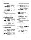
SYSTEM OFF AUTO
SUN MON TUE WED THU FRI SAT WAKELEAVERETURNSLEEP TEMPORARY VENT
AM
PM
AUTO
ON
CIRC
FAN
AUX HEAT SET PT COOL SET PT
M6400
SYSTEM
CHECK
70 F
60 F
SLEEP
WAKE
SETPOINT
TEMPERATURE
ACTUAL
TEMPERATURE
M6404