


c701
!?A
INSTALLATION
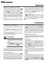
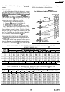
Fig.
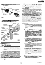
8-installing
lead sulfide photocell.
CAP
\
, MOUNTING
PLUG-IN LEAD SULFIDE CELL
(PART NO. 104662D)
METAL CABLE
SHIELDS LEADWIRES
PHOTOCELL
SOCKET
EPOA
FOCUSING LENS
I
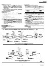
Fig. O-Mounting
C7015A
Infrared Flame
Detector (and accessories).
-J
REFRACTORY
/
MAIN
COMEUSTlON
FLAME
CHAMBER WALL
TEMPORARY
TACK
wLO\
p,T
FLARED HOLE
-3/4
INCH BLACK
IRON SIGHTING PIPE
TO JUNCTION
80X
OR SUBBASE
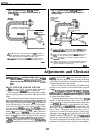
M304.5
WIAmG
(F&s.
10
and 11)
d.
/\
I CAUTION
.
Disconnect power supply before beginning instal-
lation to prevent electrical shock and equipment
damage; there may be more than one disconnect
involved.
1. All wiring must comply with applicable electrical
codes, ordinances,
and
regulations.
Use
NRC
Class 1 wiring.
,2.
Keeptheleadwiresfromtheflamedetectortotheflame
safeguard control subbase as short as possible. Capacitance
increases with
leadwire
length, reducing the signal strength.
The maximum permissible
leadwire
Iength is fifty feet.
The
ultimate
limhingfactor
in
leadwire
length is
the
frame
signal
current/voltage.
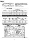
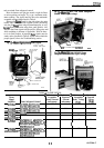
Refer to Table 6, Adjustments and Check-
out, page
10.
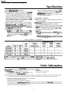
3. The detector comes with
30,48,
or
96
in.
[0.76,1.22,
or 2.44
m]
leadwires inside a flexible metal cable. The
leadwires consist of a twisted pair-one brown and one
white. The two no. 18 AWG flexible-tinned leadwires are
rated for
194’
F
[90”
C]. The cable protects and electrically
shields the leadwires.
4. If the leadwires are not long enough to reach the
terminal strip or wiring subbase, make the required splices in
a junction box (see IMPORTANT below).
5. If splicing is necessary, use moisture-resistant no. 14
wire suitable
for
at
least 167” F
[75”
C]
if
the
detector is used
withaflamesafeguardprimarycontrol,oratleast 194°F
[90”
C] if used with a flame safeguard
programming
control.
6.
For splicing in high temperature installations, use
Honeywell specification no.
R1298020
or equivalent for the
F leadwire. (This wire is rated up to 400” F
[204”
Cl
for
continuous duty. It is tested for operation up to 600 volts and
breakdown up to
7500
volts.) For the other leadwire, use
moisture-resistant no. 14 wire selected for a temperature
rating above the maximum operating temperature.
IMPORTANT:
a.
6.
C.
‘e.
f
Flame detector leadwires must be as short
aspos-
sible. The maximum
leadwire
lengthfrom
thejlame
detector to the
flame
safeguard control is 50
ft
[15.2
m].
Extensions to
the
flame
detector leadwires must be
run alone in either rigid orflexible metal
conduit.
When
frame
detector leadwires exit a conduit, they
must be as short as possible, twisted, and not be
included in bundles or channels that contain other
wires. Rigid metal conduit
is
preferred
when
flame
detector leadwires are extended
butflexible
metal
conduit may be used
tfit
is supported to minimize
movement.
The
jlame
detectorjlexible
cable shield must be
grounded to
the
flame
safeguard control subbase
either directly or through the metal cabinetlconduit
system that contains
the
flame safeguard control
subbase
andjlame
detector leadwires.
When
flame
detector leadwires are routed through
junction boxes,
identifr
the junction boxes with the
pressure-sensitive labels provided wiih the flame
detector
cform
96-610).
UNDERWRITERS LABORATORIES INC.
RE-
QUIRES THAT THE JUNCTION BOX BE
MARKED TO INDICATE
THATNO
OTHER WIR-
ING CONNECTIONS CAN BE ROUTED
THROUGH IT. APPLY CAUTION STICKER
(FORM
96410,
FURNISHED) TO THE JUNC-
TION BOX.
Maximize the separation between ignition trans-
former high voltage wires and the
jlame
sensor
wires to avoid ignition interference.
9
60-2306-5