


C7015A
INSTALLATION
l
ADUSTMENTS AND CHECKOUT
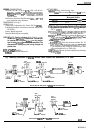
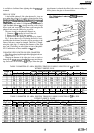
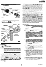
Fig. 1 O-Typical wiring of
C7015A
Infrared
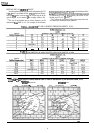
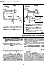
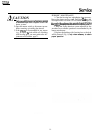
Fig. 1 l-Typical wiring of
C7015A
Infrared
Flame Detector to nearby wiring subbase or Flame Detector to distant wiring subbase or
terminal
strip.
terminal strip.
cmi5A
FLEXIBLE CABLE
(MECHANICALLY
SUPPORT TO
MINIMIZE
MOVEh
FLEXIBLE CABLE (MECHANICALLY
SUPPORT TO MINIMIZE MOVEMENT)
BX CABLE, SHIELDED
CABLE, OR TWISTED
PAIR; MUST BE ALONE
I
I
IN CONDUIT.
FLAME SAFEGUARD
CONTROLS SUBBASE
RING
SUBBASE
GROUNDlNG
STRAP,
OR
TERh
n
1
1 BROWN WIRE AND 1 WHITE WIRE FROM THE
C7015A.
CONNECT TO
FLAME SAFEGUARD CONTROL’S SUBBASE, COLOR NOT IMPORTANT,
KEEP WIRES AS SHORT AS POSSIBLE. AND TWIST THEM.
AFLEXIBLE
CABLE MUST BE RUN To
FLAME
SAFEGUARD CONTROL’S
SUBBASE AND GROUNDED WHERE THE EXPOSED WIRES BEGIN.
I
I
JUNCTION BOX
A
1 BROWN WIRE AND 1 WHITE WIRE FROM THE
C7015A;
CONNECT
lNSlDE
JUNCTlON
Box;
COLOR NOT IMPORTANT; LEADWIRES
FROM JUNCTION BOX NEED NOT BE PHASED OR POLARIZED.
APPLY CAUTION STICKER, FORM NO.
96-610
SUPPLIED WITH
Ci’O15A.
TO THIS JUNCTION BOX. BOX MUST BE GROUNDED.
USE RIGID CONDUIT. OR SUPPORT FLEXIBLE CONDUIT TO
.MINIMIZE
MOVEMENT.
CONDUIT MUST BE RUN TO FLAME SAFEGUARD CONTROL’S
SUBBASE AND GROUNDED THERE. KEEP EXPOSED WIRES AS
SHORT AS POSSIBLE AND TWIST THEM.
IA3046
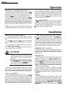
Adjustments and Checkout
IMPORTANT:
Before
welding the sight pipe in its
final
amplifEr
should blink at
the
same rate that the flame is
location,
complete
the
AdjustmentsandCheckout
Tests
flickering (may be as high as 20 times a second). If the lamp
below and any tests required by the burner
man@ac-
is ON (bright) continuously or not blinking while measuring
turer.
the flame current, replace the amplifier.
ADJUST DETECTOR SIGHTING POSITION
For
initial burner lightoff, consult the burner manufacturer
instructions or flame
safeguatd
control instructions.
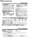
Refer to Table 6 for the minimum acceptable flame
currents for the amplifiers and associated flame safeguard
controls.
With the flame detector installed and the burner running,
adjust the sighting position of the detector
for
optimum flame
signal.
The
R7748B
AMRLI-CHECKTM
;
R7848A
and
R7848B
(AMPLI-CHECKTM)amplifiersusedwiththeBCS7700and
7800 SERIES flame safeguard controls respectively, have a
dc voltage flame signal output.
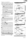
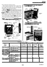
Most existing Honeywell flame safeguard controls have a
flamecurrentjackonthecontrolplug-inflameamplifier.The
flame signal (current) can be measured
with
a volt-ohmmeter
such as the Honeywell W 136A with a zero to 25 microampdc
scale. To measure the flame current (signal), a Cable Connec-
tor (part number
1%146,
included with
W136A)
must be
used with the meter. With the
W136A
(or equivalent) posi-
tioned to the zero to 25
microamp
scale, make connections
from the meter probes to the two ends of the cable connector
plug, red to
ted,
black to black The plug end of the connector
pluginsertsdirectlyintotheamplifierflamejack(seeFig. 12).
If
the
flame safeguard control is using a
R7248B
AMRLI-
CHECP
amplifier, the red flame-indicating lamp on the
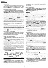
To measure flame signal voltages when using a
R7748B
amplifier, a 20,000 ohm/voltmeter with a zero to 5 or 10 Vdc
scale is suggested To measure the flame signal voltage when
using
R7848A,B
amplifiers, a volt-ohm meter with a mini-
mum sensitivity of one
megohm/volt
is recommended. The
flame signal (voltage) measurements are made as shown in
Figs. 13 and 14. The positive (red) meter lead is
connected to
the
positive (+) control jack and the negative (black) meter
lead to the negative
(-)
control jack (Corn jack with 7800
SERIES controls). If the BCS 7700 and
7800
SERIES
controls have the Keyboard Display Module, a zero to five
Vdc voltage is displayed on the module. Refer to Table 6 for
minimum and maximum flame voltages for the amplifiers