


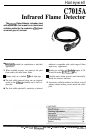
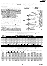

C7015A
ADJUSTMENTS AND CHECKOUT
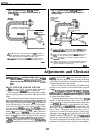
PILOT TURNDOWN TEST
Ifthedetectorisusedtoproveapilotflamebeforethemain
fuel
valve(
can be opened, perform a Pilot Turndown Test
before welding the sight pipe into position. Follow the
procedures in the instructions for the appropriate flame
safeguard control, and
the
burner manufacturer instructions.
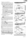
HOT REFRACTORY SATURATION TEST
Testtobesureradiationfromhotrefractorydoesnotmask
the flickering radiation of the
l&me
itself.
Start the burner and monitor the flame signal during the
warmupperiod.Adecreaseinsignalstrengthastherefmctory
heats up indicates hot refractory saturation. If saturation is
extreme, the flame relay 2K (in the flame safeguard control)
will drop out and the system will shut down as though a flame
failure has occurred.
If hot refractory saturation occurs, the condition must be
corrected. Add an orifice plate in front of
the
photocell to
restrict the viewing area. If this does not work, resight the
detector at a cooler, more distant background. Lengthening
the sight pipe or decreasing the pipe size (diameter) may also
be helpful. Continue adjustments until hot refractory satura-
tion is eliminated.
HOT REFRACTORY HOLD-IN TEST
Test to make certain that hot refractory will not cause the
flame relay 2K (in the flame safeguard control) to stay
pulled-
in after
the
burner flame is extinguished. This condition
would delay response to flame failure and also would prevent
a system
restart
as
long as the infrared radiation emitted by the
hot refractory is detected.
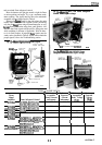
First check the plug-in flame signal amplifier by initiating
a burner cycle. When the programmer stops in the run
position, terminate the firing cycle while the refractory is at
a low temperature. Measure
the
time it takes for the flame
relay 2K to drop out after
the
flame goes out. Watch or listen
to the
flame
relay to determine when it drops out. If the flame
relay fails to drop out within four seconds, open the master
switch and replace the amplifier.
Infrared detectors can respond to infrared radiation emit-
ted by a hot refractory, even when the refractory has visibly
ceased to glow. Infrared radiation from a hot refractory is
steady, whereas radiation from a flame has a flickering
characteristic.Theinliareddetectionsystemrespondsonlyto
a flickering infrared radiation; it can reject a steady signal
from hot refractory. However, the refractory’s steady signal
can be made to fluctuate if it is reflected, bent, or blocked by
smoke or fuel mist within the combustion chamber. Be
careful when applying an infrared system to ensure its
response to flame only.
To check a
C7015A
Inj-ared
Flame Detector for hot
refractory hold-in, operate the burner until the refractory
reaches its maximum temperature. If the installation has a
multifuel burner, burn the fuel most likely to reflect, bend, or
obscure the hot refractory’s steady infrared radiation, (burn
12
solids instead of liquids, or liquids instead of gases.) When
the
maximum refractory temperature is reached, close all
manual fuel shutoff valves or open theelectricalcircuit of all
automatic fuel valves. Visually observe when the burner
flame goes out. After the flame goes out, measure the time it
takes for the flamerelay 2K to drop out. Watch or listen to the
flame relay to determine when it drops out. If the flame relay
fails to drop out within four seconds, the infrared detector is
sensing theradiation from hot refractory. Immediately termi-
nate the firing cycle, (lower the set point of the burner
controller, or set the fuel selector switch to OFF). Do not open
the master switch.
NOTE:
Some burners continue to purge their oil lines be-
tween
the
valves
and nozzles even though the fuel valve(s)
is closed. Terminating the firing cycle (instead of opening
the master switch) will allow purging of the combustion
chamber. This will reduce a buildup of fuel vapors in the
combustion chamber caused by oil line purging.
If the detector is sensing hot refractory radiation, the
condition must
bc
corrected. Add an orifice plate in front of
the photocell to restrict the detector viewing area. If this does
not work, resight the detector at a cooler, more distant part of
the combustion chamber. While resighting the detector,
remember that it must also properly sight the flame. Length-
ening the sight pipe or decreasing the pipe size (diameter)
may also be helpful. For details, refer to Installation. Con-
tinue adjustments until hot refractory hold-in is eliminated.
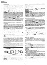
IGNITION INTERFERENCE TEST
It is possible for infrared amplifiers to respond to ignition
spark electrical noise (interference) under certain conditions.
Avoid ignition interference by locating the transformer as
close as possible to the burner ignition electrode (preferably
not on the control cabinet). You can also use an ignition cable
that suppresses electrical noise (such as the type of cable
used
in automobiles). Maintain maximum separation of flame
sensor and ignition wiring.
To determine if an infrared flame amplifier responds to
ignition interference, complete the following test sequence:
1.
CLOSE MANUAL
FLJBL
VALVES TO THE PILOT
AND MAIN
BURNER.
2.
Connect a flame signal meter to the amplifier and start
the burner.
3. There should be no flame signal when the ignitor is
energized (momentary meter movement may
be
observed
when the flame safeguard control switches a load on or off).
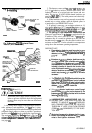
WELD THE SIGHT PIPE
After adjustments have been made and an acceptable
flame signal obtained, remove the detector and weld the sight
pipe in
its
final position, (if you are using a swivel mount, the
pipe may already be welded). Then reinstall the detector.