


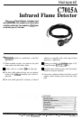

C7015A
TABLE OF CONTENTS
Table of Contents
Page
Application and Features
1
..................................................................................................................................................
1
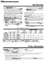
Specifications
......................................................................................................................................................................
2
Ordering Information
..............................................................................................................................................
2
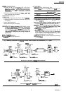
Dimension Drawings
................................................................................................................................................
3
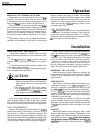
Operation
............................................................................................................................................................................
4
Installation
..........................................................................................................................................................................
4
Basic Requirements
..................................................................................................................................................
4
Installing
the Sight Pipe
...........................................................................................................................................
8
Installing Accessories
................................................................................................................................................
8
Mounting the Detector
.............................................................................................................................................
8
Wiring
.......................................................................................................................................................................
9
Adjustments and Checkout
.............................................................................................................................................
10
Troubleshooting
...............................................................................................................................................................
13
Service
..............
..~.~“~.....~.~.“.........~....................................................................................................~ .........................
14
Periodic Maintenance
.............................................................................................................................................
14
Tables
Table I -Models available
.......................................................................................................................................
2
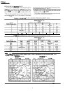
Table 2 -Diameter of area sighted through various lengths of
3/4
inch pipe without orifice, in in..
...................
.5
Table 3 -Diameter of area sighted through various lengths of
3/4
inch pipe without orifice, in mm
..................
.
Table 4 -Diameter of area sighted through orifice, in in
.......................................................................................
6
Table 5 -Diameter of area sighted through orifice, in mm
....................................................................................
6
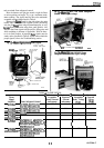
Table 6 -Flame Signal
............................................................................................................................................
11
Figures
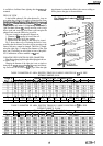
Fig.
1
-Mounting dimensions of
C7015A
Infrared Flame Detector and
accessories,
inin.
[mm].
...................
.3
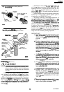
Fig. 2 -Methods of reducing
C7015A
Infrared Flame Detector field-of-view
...................................................
5
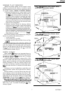
Fig. 3 -Using orifice plate to restrict detector field-of-view to intersection of pilot
and main
flame,
or to small area of hot refractory
.................................................................................
6
Fig. 4
-C7015A
Infrared Flame Detector aimed at side wall of combustion chamber
......................................
7
Fig. 5
-C7015A
Infrared Flame Detector aimed at a point above refractory
....................................................
7
Fig. 6
-C7015A
Infrared Flame Detector aimed at floor of combustion chamber
............................................
7
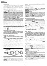
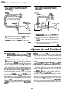
Fig. 7 -Forced air cooling
.....................................................................................................................................
8
Fig. 8 -Installing lead sulfide photocell
................................................................................................................
9
Fig. 9 -Mounting
C7015A
Infrared Flame Detector and accessories
................................................................
Fig. 10 -Typical wiring of
C7015A
to nearby wiring subbase or terminal strip
...............................................
13
Fig. 11 -Typical wiring of
C7015A
to distant wiring subbase or terminal strip
................................................
10
Fig. 12 -Measuring
microamp
ilame
signal
........................................................................................................
11
Fig. 13 -Measuring BCS 7700 Flame Safeguard Control flame signal voltage
.................................................
11
Fig. 14 -Measuring 7800 SERIES Flame Safeguard Control
Rame
signal voltage
...........................................
11
15
60-2306-5