


C7015A
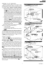
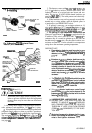
ADJUSTMENTS AND CHECKOUT
and associated flame safeguard controls.
Move the detector and
sight
pipe around to sight the flame
at various positions and angles. Try to get a maximum steady
meter reading. The signal must be above the minimum
acceptable current/voltage listed in Table 6.
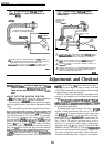
Measure the
fIame
signal for the pilot alone, the main
burner flame alone, and both together (unless monitoring
only the pilot
flame
when using an intermittent pilot, or only
themain
burner
flame
when using direct spark ignition). Also
measure the flame signal at high and low firing rates and
while modulating in between (as applicable). With the detec-
tor in its final position, all required
fhune
signals must be
steady and as specified in Table
6. If you
cannot obtain the
proper signals, refer to the Troubleshooting section.
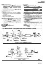
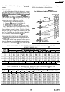
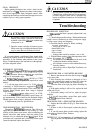
Fig. 12-Measuring
microamp
flame Signal.
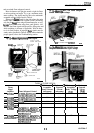
PLUG-IN FLAME
SIGNAL AMPLIFIER
I
W136A
SELECTOR
TEST
METER
SWITCH,
196146 METER
CONNECTOR
RED CONNECTOR
CK CONNECTOR
METER‘
LEAD
El 208
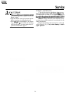
Fig. K&Measuring BCS 7700 Flame Safeguard
Control flame signal voltage.
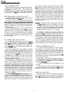
\
PROBES
\
ECS
7700
CHASSIS MODULE FOOTMOUNT
E2512A
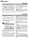
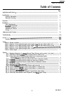
Fig. 14-Measuring 7800 SERIES Flame
Safeguard Control flame signal voltage.
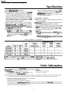
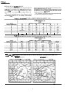
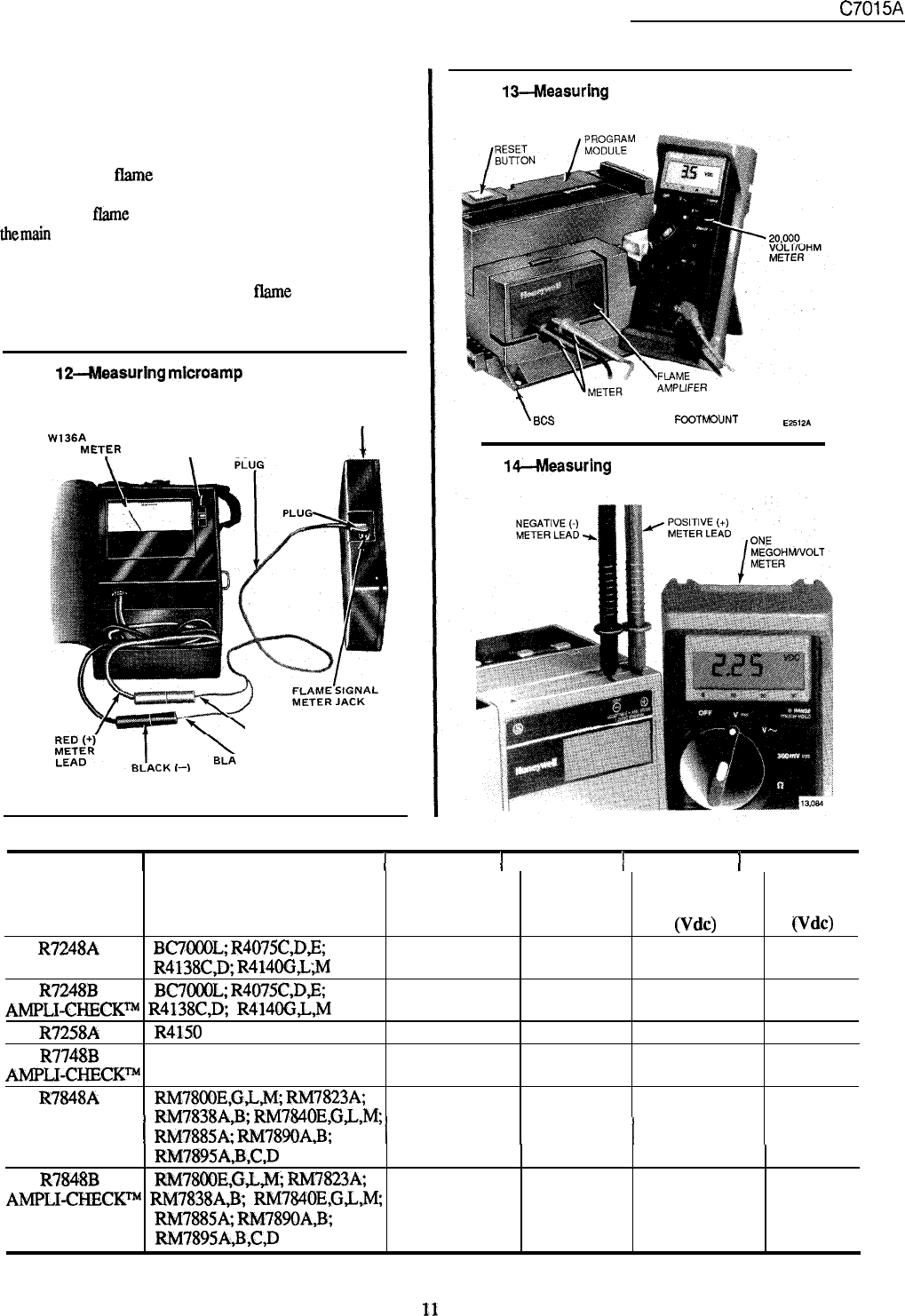
TABLE 6-FLAME SIGNAL
1
Minimum
1
Maximum
1
Minimum
1
Maximum
Flame
Acceptable Expected
Acceptable
Expected
Signal
Steady Current
Current
Steady Voltage
Voltage
Amplifier Flame Safeguard Control (microamp)
(microamp)
(Vb)
(Vdc)
R7248A
BC7OOOL;
R4075C,D,E;
2.25 5.0
R4138CD;
R414OG;L;M
R7248B
BC7OOOL;
R4075C,D,B; 3.5 5.0
AMF’LI-CHECK~
R4138CD;
R414OGL.M
R7258A R4150
4.0
5.5
R7748B
BCS 7700
2.2
4.98
AMPLI-CHECKTM
R7848A
RM78OOE,G,L,M;
RM7823A;
1.25
5.0
I
RM7838A,B;
RM784OE,G,L,M
RM7885A:
RM789OA,B;
RM7895A;B,C,D
I
I
R7848B
RM78OOE,G,L,M;
RM7823A;
1.25
5.0
AMPLI-CHECX=
RM7838AB;
RM784OE,G,L,M;
RM7885A;
RM789OA,B;
RM7895A,B,C,D
11
60-2306-5