


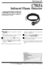

C7015A
INSTALLATION
CLEARANCE
Make sure there will be enough mom to easily mount the
sight pipe, flame detector, and all required accessories, and to
remove th e
flame
detecto r for troubleshooting and servicing.
INSTALLING THE SIGHT PIPE
Thelocationofthesightpipeisthemostcriticalpartofthe
installation. A
3/ 4
in. black iron sight pipe is recommended.
Do
rwt
use
a stainless steel or galvanized pipe because its
internal surface blackens with use as deposits from the
combustion chamber accumulate on it. Initially, its shiny
intemalsurfacereflectsinharedradiation, whichcouldresult
in a satisfactory flame signal even though the pipe may be
improperly located. As it blackens, less
inhare d
radiation is
reflected and the
flam e
signal becomes marginal.
Because no two situations
a m
the same, the length and
sighting angle of the pipe must be determined at the time and
placeofinstallation.Generally,itisdesirabletohavethesight
pipe tilting downward to prevent soot or dirt buildup.
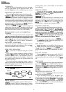
PREPARE HOLE IN WALL OF COMBUSTION
CHAMBER
Form a hole of the proper diameter for the sight pipe in the
walioftbecombustionchamberattheselectedlocation.Flare
the
hole (Fig. 9) to leave room for small adjustments of the
sighting angle. The taper of the hole should be about 1 in. for
every 3 in.
125. 4
mm for every 76.2 mm] of wall thickness.
INSTALLING ACCESSORIES
It may be necessary or desirable to install accessories
between the sight pipe and the detector. This section
de-
scribes the installation of these accessories.
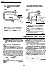
SIGHT PIPE VENTILATION
It
may be necessary to ventilate the sight pipe to cool the
detector.
For a negative pressure combustion chamber, drilling a
few holes in
the
section of the sight pipe outside of the
combustion chamber allows air at atmospheric pressure to
flow through the sight pipe into the chamber. A perforated
pipe nipple between the sight pipe and the flame detector can
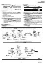
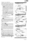
also be used. See Fig. 7.
For a positive pressure combustion chamber, connect a
supply of pressurized air from the burner blower to flow
throughthesightpipeintothechamber.Theairpressuremust
be greater than the chamber pressure.
Fig.
7-Forced
air
cooling.
mounting details, refer to form 60-0361 for the 118367A
Swivel Mount)
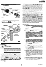
REDUCER BUSHING
To mount the detector on a l/2 in. sight pipe,
speci&zlly
if replacing a
FireyeW
lead
sulfuie
detector, install a
390427 A
Reducer Bushing (Fig. 1).
ORIFICE PLATE
To reduce the detector field-of-view, and restrict it to the
intersection of the pilot and main flame, or to a small area of
hotrefractory (see Fig.
3),
install a 105 134 Orifice Plate. The
or&e
plate can be inserted into a standard
3/ 4
in. pipe
coupling (Fig. 1) or into the seal-off adapter, if used.
MOUNTING SIGHT PIPE
Thmadoneendofthepipetofitthemountingcollaronthe
detector (or an accessory, if used, see Fig. 1). Cut the pipe to
the desired length (as
short
as
practical). T o
avoid conducting
excessive heat back to the lead
sulfide
photocell, the sight
pipeshould not extendmore than halfway
into
the refractory.
Tack weld
the
pipe to the wall in a trial position (Fig. 9) .
Do
not
permanently weld the sight pipe in place until ajter
completing the Adjustments and Checkout, page 10.
NOTE: If you use a Swivel Mount (part no.
118367A )
and
yo u
arepositive
about the location and sighting angle, you
can permanently weld the pipe.
PIPE NIPPLE
A
3/ 4
in. pipe nipple, 6 to 8 in.
[
152 to 203 mm] long, can
be inserted between the sight pipe and the
C7015 A
Mount
(Fig.
1)
to help cool the lead
sulfid e
cell. Usin g
the
pip e
nipple
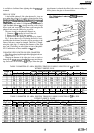
will also reduce the viewing area of the detector, see Table 2
or 3).
SEAL-OFF ADAPTER
To protect
the
detector from hot gases, install a 105 172A
Seal-Off Adapter (Fig. 1). The adapter has a glass window
that prevents hot gases from reaching the lead sulfide
photo-
cell.
HEAT BLOCK
To insulate the detector from sight pipe temperatures
above 125” F
[52”
Cl,
install a 105061 Heat Block (Fig. 1).
The device is made of nonheat-conductive, laminated plastic
that prevents heat
hor n
being conducted from the sight pipe
to the detector. It can withstand temperatures up to 250” F
[121 °
C].
DETECTOR
PIPE NIPPLE
PIPE TEE
SIGHT
”
PIPE
MOUNTING THE DETECTOR
+@a
Before mounting the
C7015A ,
install the lead sulfide
photocell (if not installed already).
COOLING AIR
APPLIED UNDER
Unscrew the bushing from the cap, plu g
the
photocel l into
the
cell mount, and screw the bushing back into the cap (Fig.
8). The bushing also includes a
focu&n g
lens to
concenuate
available radiation on the photocell face.
Mount the
C7015 A
Detector onto the sight pipe, heat
block, orotheraccessory (Figs. 1 and 9). Screw the mounting
collar onto the sight pipe or accessory.
SWIVEL MOUNT
To facilitate flame sighting, a Swivel Mount (part no.
118367A )
is available. The Swivel Mount requires a reducer
of the proper size to mount it onto the sight pipe. (For
8