


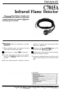
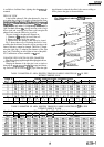
C7015A
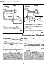
ADJUSTMENTS AND CHECKOUT
l
TROUBLESHOOTING
n
!
CAUTION
FINAL CHECKOUT
Before putting the burner into service, check out the
installation by using
the
Checkout procedures in the instruc-
tions for the appropriate flame safeguard control. After
completing the checkout, run the burner through at least one
complete cycle to verify proper operation.
Do not put the system into operation until all
Checkout tests in the instructions for the appropri-
ate flame safeguard control and any specified in the
burner installation instructions are satisfactorily
completed.
Troubleshooting
A
!
CAUTION
,
v
\
1. Be extremely careful while troubleshooting the
detector; line voltage is present on some of the
terminals on the wiring
subbase
or
terminal strip
when power is on.
2. Open the master switch to disconnect power
before removing or installing the detector, there
may be more than one disconnect involved.
If you cannot obtain a satisfactory flame signal while
adjusting the sighting position of the detector, follow these
procedures. If you encounter other problems in the system,
refer to Troubleshooting in the instructions for the appropri-
ate flame safeguard control.
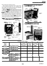
EQUIPMENT REQUIRED
1.
Voltmeter(HoneywellW136Aorequivalent)withOto
300 Vat scale.
2. Microammeter (Honeywell
W136A
or equivalent)
with 0 to 25 microampdc range.
3.
W136ACableConnector,partno.
196146, or 117053
Meter Connector Plug or equivalent (required for some
meters).
4.A volt-ohm meter with a zero to 5 or 10 Vdc scale and
a sensitivity of 20,000 ohm/volt is suggested for
BCS7700
control flame signal measurements. If the control has the
Keyboard Display Module option, flame voltage is displayed
on the module.
5.
A one
megohm/volt
meter with a zero to 5 or 10 Vdc
scale is recommended for 7800 SERIES control flame volt-
age measurements. If the control has the Keyboard Display
Module option, flame voltage is displayed on the module.
6. Replacement parts-see Specifications.
TROUBLESHOOTING PROCEDURES
Firstperfonn
thePreliminary
Inspection. Then follow the
applicable procedures for either a low reading or a zero
reading on the flame signal meter. After reinstalling the
detector, recheck the meter reading. Adjust the position of the
detector to try to obtain the proper
fIame
signal. If the
procedures are completed and a satisfactory flame signal
cannot be obtained, replace the detector.
PRELIMINARY INSPECTION
1.
Makesurethat
the flame is properly adjusted and is not
too lean.
2. Checkfortheproperlinevoltage. Makesurethemaster
switch is closed, connections are correct, and power supply
is of the correct voltage and frequency.
3. Check the detector wiring for defects including:
. incorrect connections.
l
wrong type or size of wire.
l
deteriorated wire.
l
open circuits.
l
short circuits.
l
leakage paths caused by moisture, soot, or dirt.
4.
With the burner running, check the temperature at the
detector. If it exceeds 125” F
[52”
Cl:
add additional insulation between the wall of the
combustion chamber and the detector.
add a shield or screen to reflect radiated heat away
from the detector.
add cooling (refer to Sight Pipe Ventilation, see
Installation).
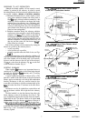
PROCEDURE FOR A LOW METER READING
1.
Remove the detector and clean the focusing lens
with
a soft, clean cloth.
2. If the focusing lens is broken or damaged, or if it is
coated with a substance that cannot be cleaned off, replace the
110634A
Bushing (which includes the focusing lens).
3.
Clean the inside of the sight pipe before reinstalling the
detector.
4. If the meter reading is still too low, replace the lead
sulfide cell (Fig. 8).
5.
If the meter reading is still too low, replace the plug-in
amplifier.
6.
If you still cannot obtain a proper flame signal, replace
the
C7015A
Infrared Flame Detector.
PROCEDURE FOR A ZERO METER READING
1.
Replace the lead sulfide cell (Fig. 8). Then recheck the
flame signal.
2. If there is still no flame signal, replace the plug-in
amplifier.
3. If you still cannot obtain a meter reading, replace the
entire
C7015A
Infrared Flame Detector.
IMPORTANT:
At the completion of troubleshooting, be
sure to perform the Adjustments and Checkout, page
10.
13
60-2306-5