


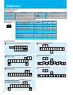
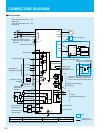
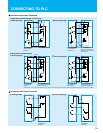

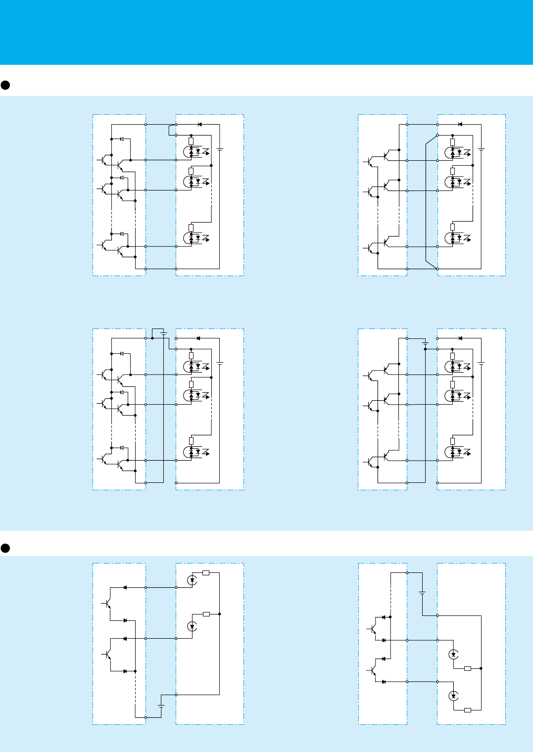
CONNECTING TO PLC
Connection with Input Terminals
Hitachi EH-150 series PLC
Output Module
EH-YT16
Inverter
Hitachi EH-150 series PLC
Output Module
EH-YTP16
Inverter
Hitachi EH-150 series PLC
Output Module
EH-YT16
Inverter
Hitachi EH-150 series PLC
Output Module
EH-YTP16
Inverter
Hitachi EH-150 series PLC
Input Module
EH-XD16
Inverter
Hitachi EH-150 series PLC
Input Module
EH-XD16
Inverter
(
1
)
Sink type logic
(
2
)
Source type logic
1.Using Internal Power Supply of The Inverter
(
1
)
Sink type logic
(
2
)
Source type logic
2.Using External Power Supply
(
1
)
Sink type logic
(
2
)
Source type logic
Connection with Output Terminals
(Note: Place short-circuit bar
between PLC and CM1 instead
of P24 and PLC)
(Note: Remove short-circuit bar
between P24 and PLC)
(Note: Be sure to turn on the inverter after turning on the PLC and its external power source to prevent the parameters in the inverter from being modified.)
(Note: Remove short-circuit
bar between P24 and PLC)
S
FW
8
1
P24
PLC
DC24V
+
- -
COM CM1
COM
FW
8
1
P24
PLC
DC24V
+
S CM1
S
FW
8
1
P24
PLC
DC24V
+
COM CM1
COM
FW
8
1
P24
PLC
DC24V
+
S CM1
DC24V
+
-
-
-
DC24V
+
-
DC24V
11
12
CM2
COM
DC24V
11
12
CM2
COM
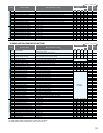
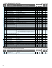
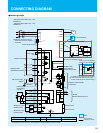
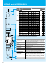
CONNECTING DIAGRAM
200V class 200V
-
240V+10%,
-
15%
50/60Hz±5%
400V class 380V
-
480V+10%,
-
15%
50/60Hz±5%
25
26
N
Sink type logic
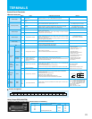
Terminal Name
Common terminal
FW, 1, 2, 3, 4, 5, 6, 7, 8, FM, TH
CM1
H, O, O2, OI, AM, AMI
L
11,12,13,14,15
CM2
R(L1)
S(L2)
T(L3)
R
T(J51)
R0
T0
(*2)Remove connection with J51
when RoTo power is supplied
externally
(*2)
Control power source
Short-circuit bar
Frequency
setting device
500
-
2kΩ
DC0
-
10V
(12bit)
DC0
-
10V(10bit)
DC
-
10
-
+10V
(12bit)
DC4
-
20mA(12bit)
DC4
-
20mA(10bit)
DC0
-
10V
Forward command
Intelligent input
terminals(8 terminals)
FM monitor output
(PWM)
AM monitor output
(Analog output)
AM monitor output
(Analog output)
(G)
P24
PLC
FW
8
7
6
1
FM
O2
OI
L
AM
AMI
10kΩ
10kΩ
100Ω
TH
H
O
RP
DC10V
Thermistor
IM
SJ700/SJ700B
CM1
(T3)W
(T2)V
(T1)U
N
P
RB
R1
R2
RB
(+1)PD
AL1
AL2
AL1
AL2
RB
P
RB
P
(+)
(
-
)
DC link choke(Note 1)
Dynamic braking unit (BRD)
(To operating circuit)
Expansion card 1
Expansion card 2
SN
SN
SP
DC24V
15
11
CM2
N
P
P
RB
P
RB
Intelligent relay
output contacts
(default:alarm output)
*1
(Inverter)
Braking resistor
(
RB
)
Intelligent output terminals
(5 terminals)
RS-485
Serial communication port
Option
Customer wiring
(Outside the inverter)
-
+
Note1:Please be sure to connect DC reactor attached to 1850HF,2200HF,3150HF and 4000HF.
The alarm relay contacts ALO and AL2
when it is in Trip Mode or when input
Power is OFF,by factory default setting.
( )
*1
SJ700: For 30kW(40HP) and over
SJ700B: For 37kW(50HP) and over
SJ700: For up to 22kW(30HP)
SJ700B: For up to 30kW(40HP)