


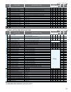
FUNCTION LIST
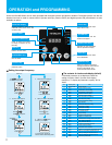
OPERATION and PROGRAMMING
-
-
-
-
-
-
-
-
-
-
-
-
-
-
-
-
-
-
-
-
-
-
-
-
-
-
-
-
-
-
-
-
-
0.00
30.00
30.00
30.00
30.00
30.00
30.00
00
-
-
-
-
-
-
-
-
-
-
-
-
-
-
-
-
-
-
-
-
-
-
-
-
-
-
-
-
-
-
-
-
-
0.00
30.00
30.00
30.00
30.00
30.00
30.00
00
-
-
-
-
-
-
-
-
-
-
-
-
-
-
-
-
-
-
-
-
-
-
-
-
-
-
-
-
-
-
-
-
-
0.00
30.00
30.00
30.00
30.00
30.00
30.00
00
A001
A002
A003
A203
A303
A004
A204
A304
A005
A006
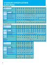
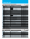
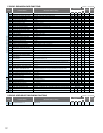
MONITORING FUNCTIONS and MAIN PROFILE PARAMETERS
Basic settings
Analog input
and others
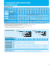
A GROUP: STANDARD FUNCTIONS
-
-
-
-
-
-
-
-
-
-
-
-
-
-
-
-
-
-
-
-
-
-
-
-
-
-
-
-
0.00
30.00
30.00
30.00
30.00
30.00
30.00
00
d001
d002
d003
d004
d005
d006
d007
d008
d009
d010
d012
d013
d014
d015
d016
d017
d018
d019
d022
d023
d024
d025
d026
d027
d028
d029
d030
d080
d090
d102
d103
d104
F001
F002
F202
F302
F003
F203
F303
F004
A---
b---
C---
H---
P---
U---
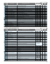
Output frequency monitor
Output current monitor
Rotation direction minitoring
Process variable (PV), PID feedback monitor
Intelligent input terminal status
Intelligent output terminal status
Scaled output frequency monitoring
Actual-frequency monitoring
Torque command monitoring
Torque bias monitoring
Torque monitoring
Output voltage monitoring
Power monitoring
Cumulative power monitoring
Cumulative operation RUN time monitoring
Cumulative power-on time monitoring
Heat sink temperature monitoring
Motor temperature monitoring
Life-check monitoring
Program counter
Program number monitoring
User monitor 0
User monitor 1
User monitor 2
Pulse counter
Position setting monitor
Position feedback monitor
Trip Counter
Trip monitoring 1-6
Programming error monitoring
DC voltage monitoring
BRD load factor monitoring
Electronic thermal overload monitoring
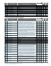
Output frequency setting
Acceleration (1) time setting
Acceleration (1) time setting, 2nd motor
Acceleration (1) time setting, 3rd motor
Deceleration (1) time setting
Deceleration time setting, 2nd motor
Deceleration time setting, 3rd motor
Keypad Run key routing
A Group: Standard functions
b Group: Fine tuning functions
C Group: Intelligent terminal functions
H Group: Motor constants functions
P Group: Expansion card functions
U Group: User-selectable menu functions
Monitor Mode
Setting Mode
Expanded Function
(Example) FW, 7, 2, 1 : ON
8, 6, 5, 4, 3 : OFF
(Example) 12, 11 : ON
AL, 15, 14, 13 :OFF
0.00 to 99.99, 100.0 to 400.0 (Hz) (*1)
0.0 to 999.9, 1000 to 9999 (A)
F (forward rotation), o (stopped), r (reverse rotation)
0.00 to 99.99, 100.0 to 999.9, 1000. to 9999. 1000 to 9999 (10000 to 99990), 100 to 999 (10000 to 999000)
0.00 to 99.99, 100.0 to 999.9, 1000. to 9999., 1000 to 3996 (10000 to 39960)
-400. to -100., -99.9 to 0.00 to 99.99, 100.0 to 400.0 (Hz) (*2)
0. to +200. (%)
-200. to +200. (%)
-200. to +200. (%)
0.0 to 600.0 (V)
0.0 to 999.9 (kW)
0.0 to 999.9, 1000. to 9999.1000 to 9999 (10000 to 99990), 100 to 999 (100000 to 999000)
0. to 9999., 1000 to 9999 (10000 to 99990), 100 to 999 (10000 to 999000) (hr)
0. to 9999., 1000 to 9999 (10000 to 99990),
100 to 999 (10000 to 999000) (hr)
-020. to 200.0 ( )
-020. to 200.0 ( )
0 to 1024
0000 to 9999
-2147483647 to 2147483647 (upper 4 digits including “-“)
-2147483647 to 2147483647 (upper 4 digits including “-“)
-2147483647 to 2147483647 (upper 4 digits including “-“)
0 to 2147483647 (upper 4 digits)
-1073741823 to 1073741823 (upper 4 digits including “-“)
-1073741823 to 1073741823 (upper 4 digits including “-“)
0. to 9999., 1000 to 6553 (10000 to 65530) (times)
Factor, frequency (Hz), current (A), voltage across P-N (V),
running time (hours), power-on time (hours)
Warning code
0.0 to 999.9 (V)
0.0 to 100.0 (%)
0.0 to 100.0 (%)
0.0, "start frequency" to "maximum frequency" (or maximum frequency, 2nd/3rd motors) (Hz)
0.0 to 100.0 (when PID function is enabled)
0.01 to 99.99, 100.0 to 999.9, 1000. to 3600. (s)
0.01 to 99.99, 100.0 to 999.9, 1000. to 3600. (s)
0.01 to 99.99, 100.0 to 999.9, 1000. to 3600. (s)
0.01 to 99.99, 100.0 to 999.9, 1000. to 3600. (s)
0.01 to 99.99, 100.0 to 999.9, 1000. to 3600. (s)
0.01 to 99.99, 100.0 to 999.9, 1000. to 3600. (s)
00 (forward rotation), 01 (reverse rotation)
Frequency source setting
Run command source setting
Base frequency setting
Base frequency setting, 2nd motor
Base frequency setting, 3rd motor
Maximum frequency setting
Maximum frequency setting, 2nd motor
Maximum frequency setting, 3rd motor
[AT] selection
[O2] selection
01 (control circuit terminal block), 02 (digital operator), 03 (RS485), 04 (option 1), 05 (option 2)
30. to "maximum frequency " (Hz)
30. to "maximum frequency, 2nd motor" (Hz)
30. to "maximum frequency, 3rd motor" (Hz)
30. to 400. (Hz) (*2)
30. to 400. (Hz) (*2)
30. to 400. (Hz) (*2)
FW
5 48 7 236 1
ON
OFF
AL
1213 1115 14
ON
OFF
2 1
ON
OFF
1: Capacitor on main circuit board
2: Cooling-fan speed drop
-
d081
d086
00 (switching between O and OI terminals), 01 (switching between O and O2 terminals),
02 (switching between O terminal and keypad potentiometer) (*1), 03 (switching between OI terminal
and keypad potentiometer) (*1), 04 (switching between O2 and keypad potentiometer) (*1)
00 (keypad potentiometer) (*1), 01 (control circuit terminal block),
02 (digital operator), 03 (RS485), 04 (option 1), 05 (option 2),
06 (pulse-string input), 07 (easy sequence), 10 (operation function result)
00 (single), 01 (auxiliary frequency input via O and OI terminals) (nonreversible),
02 (auxiliary frequency input via O and OI terminals) (reversible), 03 (disabling O2 terminal)
(*1) This setting is valid only when the OPE-SR is connected. (*2) 4000HF:30. to 120. (Hz)
(*1) 4000HF:0.00 to 99.99,100.0 to 120.0(Hz) (*2)4000HF: -120. to -100., -99.9 to 0.00 to 99.99,100.0 to 120.0(Hz)
01
01
50.
50.
50.
50.
50.
50.
00
03
01
01
60.
60.
60.
60.
60.
60.
00
03
02
02
60.
60.
60.
60.
60.
60.
00
03
01
01
50.
50.
50.
50.
50.
50.
00
03
-
-
Code
Function Name
Default Setting
-FE(CE) -FU(UL)
SJ700
SJ700B
-F(JP)
Change
during operation
(allowed or not)
Setting
during operation
(allowed or not)
Monitored data or setting
= Allowed = Not permitted
Code
Function Name
Default Setting
-FE(CE) -FU(UL)
SJ700
SJ700B
-F(JP)
Change
during operation
(allowed or not)
Setting
during operation
(allowed or not)
Monitored data or setting
= Allowed = Not permitted
*
)
Not available
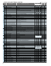
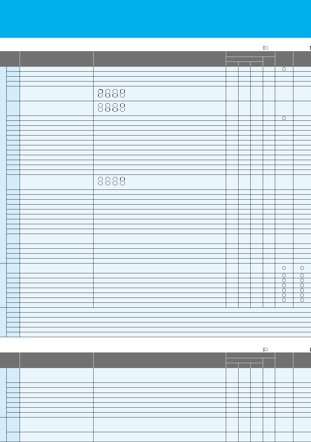
Press
until appears.
1or the value previously
monitored is displayed.
2 Function code appears.
3appears.
Power on
Press key.
Press key.
FUNC
FUNC
4 Preset value is displayed.
5 Newly set value is displayed.
6 Returns to and
the setting is complete.
Press
to set desired value.
Press key
to store the value.
To run the motor, go back to
monitor mode or basic setting mode.
STR
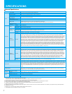
The contents of a basic mode display.(default)
Setting the output frequency
No.
1
2
3
4
5
6
7
8
9
10
11
12
13
14
15
16
17
18
19
20
21
22
23
24
25
26
27
28
29
Display code
d001 to d104
F001
F002
F003
F004
A001
A002
A003
A004
A005
A020
A021
A022
A023
A044
A045
A085
b001
b002
b008
b011
b037
b083
b084
b130
b131
C021
C022
C036
Item
Monitor display
Output frequency setting
Acceleration (1) time setting
Deceleration (1) time setting
Operation direction setting
Frequency source setting
Run command source setting
Base frequency setting
Maximum frequency setting
[AT] selection
Multi-speed frequency setting
Multi-speed 1 setting
Multi-speed 2 setting
Multi-speed 3 setting
1st control method
V/f gain setting
Operation mode selection
Selection of restart mode
Allowable under-voltage power failure time
Retry-after-trip selection
Retry wait time after trip
Function code display restriction
Carrier frequency setting
Initialization mode selection
Selection of overvoltage suppression function
Setting of overvoltage suppression level
Setting of intelligent output terminal 11
Setting of intelligent output terminal 12
Alarm relay active state
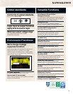
SJ700 and SJ700B Series can be easily operated with the digital operator provided as standard. The digital operator can also be
detached and can be used for remote-control. Operator with copy function (WOP) and digital operator with potentiometer are also
available as options.
Shows drive status.
Press to run the motor.
Press to stop the drive or
reset an alarm.
Lights when the power input
to the drive is ON.
Indicates the unit associated
with the parameter display.
Press to write the new value
to the EEPROM.
Press up or down to sequence
through parameters and functions
shown on the display, and
increment/decrement values.
Press to set or monitor a
parameter value.
Parameter Display Power LED
Display Unit LEDs
Lights to indicate that the
inverter has tripped.
ALARM LED
Store Key
Up/Down Keys
Monitor LEDs
Lights up when the inverter
is ready to respond to the
RUN key.
RUN key enable LED
RUN Key
STOP/RESET Key
Function Key
Displays frequency, motor current,
rotational speed of the motor, and
an alarm code.
If a desired parameter is not displayed, check the
setting of function "b037" (function code display
restriction). To display all parameters, specify "00" for
"b037".
11
12