


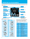


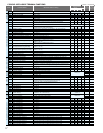

OPERATOR
U GROUP: USER-SELECTABLE MENU FUNCTIONS
no/d001 to P131
Operation mode on expansion card 1 error
Operation mode on expansion card 2 error
Encoder pulse-per-revolution (PPR) setting
Control pulse setting
Pulse input mode setting
Home search stop position setting
Home search speed setting
Home search direction setting
Home search completion range setting
Home search completion delay time setting
Electronic gear set position selection
Electronic gear ratio numerator setting
Electronic gear ratio denominator setting
Feed-forward gain setting
Position loop gain setting
Position bias setting
Temperature compensation thermistor enable
Over-speed error detection level setting
Speed deviation error detection level setting
Numerator of motor gear ratio
Denominator of motor gear ratio
Accel./decel. time input selection
Positioning command input selection
Torque command input selection
Torque command setting
Torque bias mode
Torque bias value
Torque bias polarity selection
DeviceNet comm watchdog timer
Inverter action on DeviceNet comm error
DeviceNet polled I/O : Output instance number
DeviceNet polled I/O : input instance number
Inverter action on DeviceNet idle mode
DeviceNet motor poles setting for RPM
Pulse-string frequency scale
Time constant of pulse-string frequency filter
Pulse-string frequency bias
Pulse-string frequency limit
Multistage position setting 0-7
Zero-return mode selection
Zero-return direction selection
Low-speed zero-return frequency
High-speed zero-return frequency
Position range specification (forward)
Position range specification (reverse)
Teaching selection
Easy sequence user parameter U (00)-(31)
00 (tripping), 01 (continuing operation)
00 (tripping), 01 (continuing operation)
128. to 9999., 1000 to 6500 (10000 to 65000) (pulses)
00 (ASR), 01 (APR), 02 (APR2), 03 (HAPR)
00 (mode 0), 01 (mode 1), 02 (mode 2)
0. to 4095.
"start frequency" to "maximum frequency" (up to 120.0) (Hz)
00 (forward), 01 (reverse)
0. to 9999., 1000 (10000) (pulses)
0.00 to 9.99 (s)
00 (feedback side), 01 (commanding side)
0. to 9999.
0. to 9999.
0.00 to 99.99, 100.0 to 655.3
0.00 to 99.99, 100.0
-204 (-2048.) / -999. to 2048
00 (no compensation), 01 (compensation)
0.0 to 150.0 (%)
0.00 to 99.99, 100.0 to120.0 (Hz)
0. to 9999.
0. to 9999.
00 (digital operator), 01 (option 1), 02 (option 2), 03 (easy sequence)
00 (digital operator), 01 (option 1), 02 (option 2)
00 (O terminal), 01 (OI terminal), 02 (O2 terminal), 03 (digital operator)
0. to 200. (%)
00 (as indicated by the sign), 01 (depending on the operation direction)
00 (disabling the mode), 01 (digital operator), 02 (input via O2 terminal)
-200. to +200. (%)
00 (as indicated by the sign), 01 (depending on the operation direction)
0.00 to "maximum frequency" (Hz)
0.00 to "maximum frequency" (Hz)
0.00 to 99.99 (s)
20, 21, 100
70, 71, 101
0, 2, 4, 6, 8, 10, 12, 14, 16, 18, 20, 22, 24, 26, 28, 30, 32, 34, 36, 38 (poles)
1.0 to 50.0 (kHz)
0.01 to 2.00 (s)
-100. to +100. (%)
0. to 100. (%)
Position setting range reverse side – forward side
(upper 4 digits including “-“)
00(Low) / 01 (Hi1) / 00 (Hi2)
00 (FW) / 01 (RV)
0.00 – 10.00 (Hz)
0.00 – 99.99 / 100.0 – Maximum frequency setting, 1st motor (Hz)
0 – 268435455 (when P012 = 02) 0 – 1073741823 (When P012 = 03) (upper 4 digits)
-268435455 – 0 (when P012 = 02) -1073741823 - 0 (When P012 = 03) (upper 4 digits)
00 (X00) / 01 (X01) / 02 (X02) / 03 (X03) /04 (X04) / 05 (X05) / 06 (X06) / 07 (X07)
0. to 9999., 1000 to 6553 (10000 to 65535)
P001
P002
P011
P012
P013
P014
P015
P016
P017
P018
P019
P020
P021
P022
P023
P024
P025
P026
P027
P028
P029
P031
P032
P033
P034
P035
P036
P037
P038
P039
P040
P044
P045
P046
P047
P048
P049
P055
P056
P057
P058
P068
P069
P070
P071
P072
P073
P074
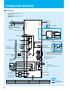
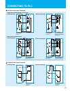
Output terminal operation function
Absolute position control
sequence
P100
I
P131
P060
I
P067
U001
I
P012
User selected functions 1-12
parameters
no no
no
no
P GROUP: EXPANSION CARD FUNCTIONS
00
00
1024
00
00
0.
5.00
00
5.
0.00
00
1.
1.
0.00
0.50
0.
00
135.0
7.50
1.
1.
00
00
00
0.
00
00
0.
00
0.00
0.00
1.00
01
21
71
01
00
25.0
0.10
0.
100.
0
00
00
0.00
0.00
00
0.
00
00
1024
00
00
0.
5.00
00
5.
0.00
00
1.
1.
0.00
0.50
0.
00
135.0
7.50
1.
1.
00
00
00
0.
00
00
0.
00
0.00
0.00
1.00
01
21
71
01
00
25.0
0.10
0.
100.
0
00
00
0.00
0.00
00
0.
00
00
1024
00
00
0.
5.00
00
5.
0.00
00
1.
1.
0.00
0.50
0.
00
135.0
7.50
1.
1.
00
00
00
0.
00
00
0.
00
0.00
0.00
1.00
01
21
71
01
00
25.0
0.10
0.
100.
0
00
00
0.00
0.00
00
0.
no
00
00
1024
00
00
0.
5.00
00
5.
0.00
00
1.
1.
0.00
0.50
0.
00
135.0
7.50
1.
1.
00
00
00
0.
00
00
0.
00
0.00
0.00
1.00
01
21
71
01
00
25.0
0.10
0.
100.
0
00
00
0.00
0.00
00
0.
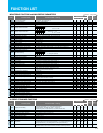
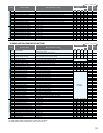
Code
Function Name
Default Setting
-FE(CE) -FU(UL)
SJ700
SJ700B
-F(JP)
Change
during operation
(allowed or not)
Setting
during operation
(allowed or not)
Monitored data or setting
= Allowed = Not permitted
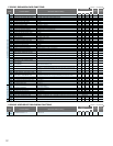
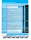
Code
Function Name
Default Setting
-FE(CE) -FU(UL)
SJ700
SJ700B
-F(JP)
Change
during operation
(allowed or not)
Setting
during operation
(allowed or not)
Monitored data or setting
= Allowed = Not permitted
Polarity selection at the torque command
input via O2 terminal
Speed limit for torque-controlled operation
(forward rotation)
Speed limit for torque-controlled operation
(reverse rotation)
00 (tripping), 01 (tripping after decelerating and stopping the motor), 02 (ignoring errors),
03 (stopping the motor after free-running), 04 (decelerating and stopping the motor)
00 (tripping), 01 (tripping after decelerating and stopping the motor), 02 (ignoring errors),
03 (stopping the motor after free-running), 04 (decelerating and stopping the motor)
268435455
-268435455
*
)
Not available for SJ700B
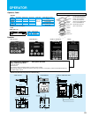
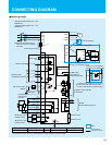
You can mount the keypad
with the potentiometer for a
NEMA1 rated installation.
The kit also provides for
removing the potentiometer
knob to meet NEMA 4X
requirements,as shown
(part no.4X-KITmini).
For Furthermore Operation
......
Use option as WOP
Main Features for WOP :
-Large LCD screen
-Real time clock
-Copy function: Storing parameter settings of a total 4 units of inverters
-Multi-language (Japanese, English and Chinese) [ Planning to expand to 10 languages ] SJ700 and SJ700B is English only.
-Selectable display contents
4X-KITmini (For combination with OPE-SR mini)
Panel
Screw
External
Gasket
Front Cover
Internal
Gasket 1
Internal
Gasket 2
Rear Cover
Cable
Cable <ICS-1,3>
L
Operator, Cable
Operator
Model
OPE-SR mini
OPE-SBK
OPE-SR
WOP
SRW-0EX
*1
Potentiometer
Model
ICS-1
ICS-3
Cable Length
1m(3.3ft)
3m(9.8ft)
Remote Control Copy function
Applied Model for Built-in
SJ200
Standard for SJ700,SJ700B
SJ700,SJ700B
SJ700,SJ700B,SJ300,L300P
SJ300,L300P
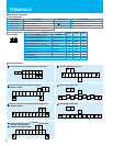
<OPE-SBK(SR)><OPE-SR mini>
<WOP>
59(2.32)
6.5
(0.26)
2(0.08)
26.5(1.04)
18(0.71)
18
(0.71)
Mounting holes
80(3.15)
79(3.11)
1
2
STOP/
RESET
FUNC
STR
RUN
PRG
RUN
Hz
V
kW
A
%
ALARM
POWER
8(0.31)
13
(0.51)
(※)
Potentiometer is installed
only in OPE-SR
2-φ(0.16)
18(0.71)
20.5(0.81)
18(0.71)
8.8(0.35)
15.3
(0.60)
16.5
(0.65)
Mounting holes
Dimentions (Unit:mm(inch) Inches for reference only)
Operator
7(0.28) 2.7(0.11)
10
(0.39)
70(2.76)
55(2.17)
2-M3 depth5(Reverse side)
2-M3 depth5(Reverse side)
POWER RUN WARNING ALARM
REMOTE OPERATOR
80(3.15)
103(4.06)
123(4.84)
8
(0.31)
13
(0.51)
6.5
(0.26)
103(4.06)
2
(0.08)
26.5
(1.04)
18(0.71)
18
(0.71)
2-φ4(0.16)
Mounting holes
REMOTE
ESC SET
OPE
KEY ENABLED
1
2
43
READ
STOP
RESET
WRITE
<SRW-0J, SRW-0EX>
FWD RUN REV RUN
<OPE-SBK(SR)><OPE-SR mini> < SRW-0J, SRW-0EX, WOP>
*1) Production has been stopped.
19
20
ICS-11m
ICS-33m
Applied Cable