


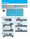
TERMINALS
W
W:Terminal width
Main Circuit Terminals
Terminal Description
R
(
L1
)
, S
(
L2
)
, T
(
L3
)
U
(
T1
)
, V
(
T2
)
, W
(
T3
)
PD
(
+1
)
, P
(
+
)
P
(
+
)
, RB
(
RB
)
Terminal Symbol
Terminal Name
Main power supply input terminals
Inverter output terminals
DC reactor connection terminals
External braking resistor connection terminals
P
(
+
)
, N
(
-
)
(
G
)
R0
(
R
0
)
, T
0
(
T
0
)
Terminal Symbol
Terminal Name
External braking unit connection terminals
Ground connection terminal
Control power supply input terminals
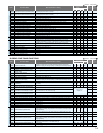
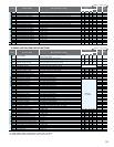
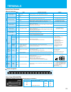
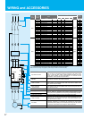
Terminal Arrangement
Screw Diameter and
Terminal Width
Model
SJ700 SJ700B
Screw
diameter
004037LFF2,LFUF2/007037HFF2,HFEF2,HFUF2
055,075LFF2,LFUF2/HFF2,HFEF2,HFUF2
110LFF2,LFUF2/HFF2,HFEF2,HFUF2
150,185LFF2,LFUF2/150-300HFF2,HFEF2,HFUF2
220,300LFF2,LFUF2
370,450LFF2,LFUF2/370-550HFF2,HFEF2,HFUF2
550LFF2,LFUF2
750,900HFF2,HFEF2,HFUF2
1100HFF2,HFEF2,HFUF2/1320HFF2,HFEF2/1500HFUF2
1850,2200HF2,HFE2,HFU2
3150HF2,HFE2,HFU2
4000HF2,HFE2,HFU2
R
0T0 terminals (All models)
-
110HFF
150HFF
185-370HFF
-
450-750HFF
-
900,1100HFF
1320,1600HFF
-
-
-
M4
M5
M6
M6
M8
M8
M10
M10
M10
M16
M16
M12
M4
Ground Screw
diameter
M4
M5
M6
M6
M6
M8
M8
M8
M8
M12
M12
M12
-
Terminal
width
mm
13
18
18
23
23
29
40
29
40
51
45
50
9
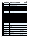
SJ700-055-220LFUF2,LFF2, HFEF2,HFUF2,HFF2
SJ700-450-550LFUF2, LFF2, 750
-1100HFEF2
, HFUF2, HFF2
1320HFEF2,HFF2/1500HFUF2
SJ700-300-370LFUF2, LFF2, 300
-
550HFEF2, HFUF2, HFF2 SJ700-4000HFE2, HFU2, HF2
SJ700-3150HFE2, HFU2, HF2
R
(L1)
S
(L2)
T
(L3)
PD
(+1)
P
(+)
N
(
-
)
U
(T1)
V
(T2)
W
(T3)
RB
(RB
R0
(R0)
T0
(T0)
(G) (G)
(G) (G)
R
(L1)
S
(L2)
T
(L3)
PD
(+1)
P
(+)
N
(
-
)
U
(T1)
V
(T2)
W
(T3)
R0
(R0)
T0
(T0)
(G) (G)
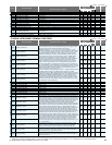
R
(L1)
S
(L2)
T
(L3)
PD
(+1)
P
(+)
N
(
-
)
U
(T1)
V
(T2)
W
(T3)
R0
(R
0)
T0
(T
0)
R
(L1)
S
(L2)
T
(L3)
PD
(+1)
P
(+)
P
(+)
N
(
-
)
U
(T1)
V
(T2)
W
(T3)
R0
(R0)
T0
(T0)
(G) (G)
R
(L1)
S
(L2)
T
(L3)
PD
(+1)
P
(+)
P
(+)
N
(
-
)
U
(T1)
V
(T2)
W
(T3)
R0
(R0)
T0
(T0)
(G) (G)
SJ700B-110-300HFF
SJ700B-370-750HFF
SJ700B-550-750LFF/900-1600HFF
SJ700-004-037LFUF2, LFF2/007-037HFEF2, HFUF2, HFF2 SJ700-1850, 2200HFE2, HFU2, HF2
R
(L1)
S
(L2)
T
(L3)
PD
(+1)
P
(+)
N
(
-
)
U
(T1)
V
(T2)
W
(T3)
R0
(R0)
T0
(T0)
(G) (G)
P
(+)
R0 T0
R
(L1)
S
(L2)
T
(L3)
U
(T1)
V
(T2)
W
(T3)
PD
(+1)
P
(+)
N
(
-
)
RB
(RB
(G)
(G)
21
22
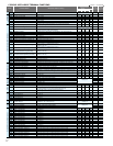
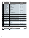
TERMINALS
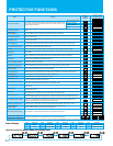
Terminal Description
Symbol
Name Explanation of Terminals Ratings
Maximum capacity of relays
AL1-AL0: AC 250V, 2A(R load)/0.2A(L load)
DC 30V, 8A(R load)/0.6A(L load)
AL2-AL0:AC 250V, 1A(R load)/0.2A(L load)
DC 30V, 1A(R load)/0.2A(L load)
Minimum capacity of relays
AL1-AL0, AL2-AL0:
AC100V, 10mA DC5V, 100mA
Power Supply
Frequency Setting
Monitor Output
Monitor Output
Power Supply
Contact
Input
Open
Collector
Output
Analog
Input
Relay
Output
Run
Command
Functions
Common
Terminal
State
Sensor
State/
Alarm
Common Terminal for Analog
Power Source
Power Source for Frequency
Setting
Frequency Command Terminal
Frequency Command Extra
Terminal
Frequency Command Terminal
Analog Output Monitor (Voltage)
Analog Output Monitor (Current)
Digital Monitor (Voltage)
Power Terminal for Interface
Allowable input voltage range
AnalogDigitalAnalogDigital
In default setting, an alarm is activated when inverter output is turned off by a
protective function.
Common terminal for H, O, O2, OI, AM, and AMI. Do not ground.
-
Input impedance: 10kΩ, Allowable
input voltage range: DC -0.3-+12V
DC 10V, 20mA max.
Input impedance:10kΩ, Allowable
input voltage range: DC 0-±12V
Maximum frequency is attained at DC 10V in DC 0-10V range. Set the voltage at
A014 to command maximum frequency below DC 10V.
O2 signal is added to the frequency command of O or OI in DC 0-±10V range. By
changing configuration, frequency command can be input also at O2 terminal.
Maximum frequency is attained at DC 20mA in DC 4-20mA range.
When the intelligent terminal configured as AT is on, OI signal is enabled.
Selection of one function from:
Output frequency, output current, torque, output voltage, input power, electronic
thermal load ratio, and LAD frequency.
[DC0-10V output (PWM output)] Selection of one function from: Output
frequency, output current, torque, output voltage, input power, electronic thermal
load ratio, and LAD frequency.
[Digital pulse output (Pulse voltage DC 0/10V)] Outputs the value of output
frequency as digital pulse (duty 50%)
Internal power supply for input terminals. In the case of source type logic,
common terminal for contact input terminals.
Common Terminal for Interface
Common terminal for P24, TH, and FM. In the case of sink type logic, common
terminal for contact input terminals. Do not ground.
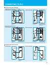
Select sink or source logic with the short-circuit bar on the control terminals.
Sink logic: Short P24 to PLC / Source logic: Short CM1 to PLC.
When applying external power source, remove the short-circuit bar and connect
PLC terminal to the external device.
Assign 5 functions to open collector outputs.
When the alarm code is selected at C062, terminal 11-13 or 11-14 are reserved
for error codes of inverter trip.
(Refer to the standard specifications for the functions.)
Both sink and source logic are always applicable between each terminal and CM1.
The inverter trips when the external thermistor detects abnormal temperature.
Common terminal is CM1.
[Recommended thermistor characteristics]
Allowable rated power: 100mW or over.
Impedance in the case of abnormal temperature: 3kΩ
Note: Thermal protection level can be set between 0 and 9999Ω.
Forward Command Input
Intelligent Input Terminals
Common Terminal for
Intelligent Input Terminals,
Common Terminal for
External Power Supply for
PLCs, etc.
Intelligent Output Terminals
Common Terminal for
Intelligent Output Terminals
Thermistor Input Terminals
Alarm Output Terminals
Power supply for frequency command input
Input impedance: 100Ω, Allowable
input voltage range: DC 0-24mA
DC 0-10V, 2mA max.
DC 4-20mA, 250Ω max.
Digital output frequency
range: 0-3.6kHz, 1.2mA max.
DC 24V, 100mA max.
The motor runs forward when FW terminal is ON,
and stops when FW is OFF.
[Input ON condition]
Voltage between each terminal
and PLC: DC 18V min.
[Input OFF condition]
Voltage between each terminal
and PLC: DC 3V max.
Input impedance between each
terminal and PLC: 4.7Ω
Allowable maximum voltage
between each terminal and
PLC: DC 27V
Decrease in voltage between
each terminal and CM2:
4V max. during ON
Allowable maximum voltage: DC 27V
Allowable maximum current: 50mA
Common terminal for intelligent output terminal 11-15.
11
12
13
14
15
AL0
AL1
AL2
1
2
3
4
5
6
7
8
O2
OI
AM
AMI
FM
TH
L
H
-
P24
CM1
FW
PLC
CM2
O
Assign 8 functions to terminals.
(Refer to the standard specifications for the functions.)
DC0
-
8V
DC8V
10kΩ
1kΩ
[
Input Circuit
]
Thermistor
TH
CM1
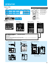
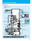
Control Circuit Terminals
Terminal Arrangement
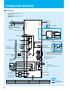
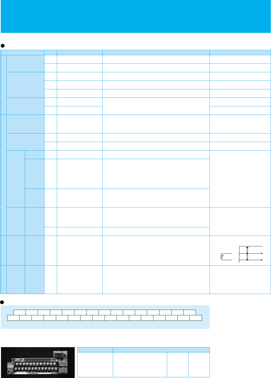
Relay Output PCB(L300PTM)
L300PTM is available in case a relay output function is nessessary.
H
L
O2
O
AM
OI
FM
AM1
TH
P24
FW
PLC
8
CM1
CM1
7
5
6
3
4
1
2
14
15
13
CM2
11
12
AL1
AL0 AL2
Screw diameter:M3 Terminal Width:6.4mm
Terminal Symbol Specifications
11A
11C
12A
12C
Contacting Maximum Rate
Contacting Minimum Rate
AC250V
DC30A
DC1V
5A
1A
5A
1A
1mA