


Active frequency matching, scan start frequency
Active frequency matching, scan-time constant
Active frequency matching, restart frequency select
Software lock mode selection
RUN/ power-on warning time
Rotational direction restriction
Reduced voltage start selection
Function code display restriction
Initial-screen selection
Automatic user-parameter setting function enable
Torque limit selection
Torque limit LADSTOP enable
Reverse RUN protection enable
Controlled deceleration and stop on power loss
DC bus voltage trigger level during power loss
Over-voltage threshold during power loss
Deceleration time setting during power loss
Initial output frequency decrease during power loss
Proportional gain setting for nonstop operation at power loss
Integral time setting for nonstop operation at power loss
Maximum-limit level of window comparators O
Minimum-limit level of window comparators O
Hysteresis width of window comparators O
Maximum-limit level of window comparators OI
Minimum-limit level of window comparators OI
Hysteresis width of window comparators OI
Maximum-limit level of window comparators OI
Minimum-limit level of window comparators O/OI/O2
Hysteresis width of window comparators O/OI/O2
Operation level at O disconnection
Operation level at OI disconnection
Operation level at O2 disconnection
Cumulative input power data clearance
Cumulative input power display gain setting
Start frequency adjustment
Carrier frequency setting
Initialization mode (parameters or trip history)
Country code for initialization
Frequency scaling conversion factor
STOP key enable
Restart mode after FRS
Automatic carrier frequency reduction
Dynamic braking usage ratio
Stop mode selection
Cooling fan control
Dynamic braking control
Dynamic braking activation level
Thermistor for thermal protection control
Thermal protection level setting
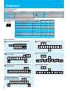
Free-setting V/f frequency (1)
Free-setting V/f voltage (1)
Free-setting V/f frequency (2)
Free-setting V/f voltage (2)
Free-setting V/f frequency (3)
Free-setting V/f voltage (3)
Free-setting V/f frequency (4)
Free-setting V/f voltage (4)
Free-setting V/f frequency (5)
Free-setting V/f voltage (5)
Free-setting V/f frequency (6)
Free-setting V/f voltage (6)
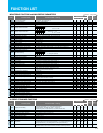
Window comparatorOthersFree setting of V/f characteristic
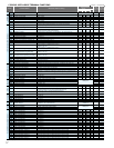
b028
b029
b030
b031
b034
b035
b036
b037
b038
b039
b040
b041
b042
b043
b044
b045
b046
b050
b051
b052
b053
b054
b055
b056
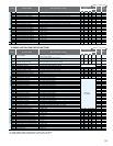
b060
b061
b062
b063
b064
b065
b066
b067
b068
b070
b071
b072
b078
b079
b082
b083
b084
b085
b086
b087
b088
b089
b090
b091
b092
b095
b096
b098
b099
b100
b101
b102
b103
b104
b105
b106
b107
b108
b109
b110
b111
0.10 to 30.00 (s)
00 (frequency at the last shutoff), 01 (maximum frequency), 02 (set frequency)
0. to 9999. (0 to 99990), 1000 to 6553 (10000 to 655300) (hr)
0 (minimum reduced voltage start time) to 255 (maximum reduced voltage start time)
00 (disabling), 01 (enabling)
00 (disabling), 01 (enabling)
00 (disabling), 01 (enabling)
00 (disabling), 01 (enabling)
0.0 to 999.9, 1000. (V)
0.0 to 999.9, 1000. (V)
0.01 to 99.99, 100.0 to 999.9, 1000. to 3600. (s)
0.00 to 10.00 (Hz)
0.00 to 2.55
0.0 to 9.999 /10.00 to 65.55
0. to 100. (lower limit : b061 + b062*2) (%)
0. to 100. (lower limit : b060 - b062*2) (%)
0. to 10. (lower limit : b061 - b062 / 2) (%)
0. to 100. (lower limit : b064 + b066*2) (%)
0. to 100. (lower limit : b063 - b066*2) (%)
0. to 10. (lower limit : b063 - b064 / 2) (%)
-100. to 100. (lower limit : b067 + b068*2) (%)
-100. to 100. (lower limit : b066 - b068*2) (%)
0. to 10. (lower limit : b066 - b067 / 2) (%)
0 to 100 (%) or "no" (ignore)
0 to 100 (%) or "no" (ignore)
0 to 100 (%) or "no" (ignore)
Clearance by setting "01" and pressing the STR key
1. to 1000.
0.10 to 9.99 (Hz)
00 (Japan), 01 (EU), 02 (U.S.A.)
0.1 to 99.0
00 (enabling), 01 (disabling), 02 (disabling only the function to stop)
00: invalid, 01: valid
0.0 to 100.0 (%)
00 (deceleration until stop), 01 (free-run stop)
330 to 380, 660 to 760(V)
0. to 9999. ( )
0. to "free-setting V/f frequency (2)" (Hz)
0.0 to 800.0 (V)
0. to "free-setting V/f frequency (3)" (Hz)
0.0 to 800.0 (V)
0. to "free-setting V/f frequency (4)" (Hz)
0.0 to 800.0 (V)
0. to "free-setting V/f frequency (5)" (Hz)
0.0 to 800.0 (V)
0. to "free-setting V/f frequency (6)" (Hz)
0.0 to 800.0 (V)
0. to "free-setting V/f frequency (7)" (Hz)
0.0 to 800.0 (V)
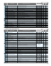
(*1) “Over current protection” , ” Overload restriction” , “Over current limiting” and “Electronic thermal protection” might operate from the set value when “Carrier frequency setting” is used
with less than 2kHz by a low value. Please set to 2kHz or more and use the setting of “Carrier frequency setting” for such a situation. (*2) 1850HF, 2200HF and 3150HF:2.1, 4000HF:1.9
0.50
00
01
0.
00
06
04
01
00
00
150.
150.
150.
150.
00
00
00
220.0/440.0
360.0/720.0
1.00
0.00
0.20
0.100
100
0
0
100
0
0
100
-100
0
255(no)
255(no)
127(no)
00
1.
0.50
5.0(*2)
00
01
1.0
00
00
00
0.0
00
00
00
360/720
00
3000.
0.
0.0
0.
0.0
0.
0.0
0.
0.0
0.
0.0
0.
0.0
0.50
00
01
0.
00
06
04
01
00
00
150.
150.
150.
150.
00
00
00
220.0/440.0
360.0/720.0
1.00
0.00
0.20
0.100
100
0
0
100
0
0
100
-100
0
255(no)
255(no)
127(no)
00
1.
0.50
5.0(*2)
00
02
1.0
00
00
00
0.0
00
00
00
360/720
00
3000.
0.
0.0
0.
0.0
0.
0.0
0.
0.0
0.
0.0
0.
0.0
0.50
00
01
0.
00
06
04
01
00
00
150.
150.
150.
150.
00
00
00
220.0/440.0
360.0/720.0
1.00
0.00
0.20
0.100
100
0
0
100
0
0
100
-100
0
255(no)
255(no)
127(no)
00
1.
0.50
5.0(*2)
00
00
1.0
00
00
00
0.0
00
00
00
360/720
00
3000.
0.
0.0
0.
0.0
0.
0.0
0.
0.0
0.
0.0
0.
0.0
0.50
00
01
0.
00
06
04
01
00
00
120.
120.
120.
120.
00
00
00
220.0/440.0
360.0/720.0
1.00
0.00
0.20
0.100
100
0
0
100
0
0
100
-100
0
255(no)
255(no)
127(no)
00
1.
0.50
3.0(*1)
00
01
1.0
00
00
00
0.0
00
00
00
360/720
00
3000.
0.
0.0
0.
0.0
0.
0.0
0.
0.0
0.
0.0
0.
0.0
Others
Torque limitation
Non-stop operation at
momentary power failure
software
lock
00 (disabling change of data other than "b031" when SFT is on), 01 (disabling change
of data other than "b031" and frequency settings when SFT is on), 02 (disabling change
of data other than "b031"), 03 (disabling change of data other than "b031" and
frequency settings), 10 (enabling data changes during operation)
Rated current of inverterx 1..0
SJ700: 0.20 x "rated current" to 2.00 x "rated current" (A) < 75kW and over:0.20 x 1.50 >
SJ700B: 0.20 x "rated current" to 1.50 x "rated current" (A)
00 (enabling both forward and reverse rotations), 01 (enabling only forward rotation),
02 (enabling only reverse rotation)
00 (full display), 01 (function-specific display), 02 (user setting), 03 (data comparison
display), 04 (basic display)
00 (screen displayed when the STR key was pressed last), 01 (d001), 02 (d002),
03 (d003), 04 (d007), 05 (F001)
SJ700: 0. to 200. (%), no (disabling torque limitation) < 75kW and over:0. to 180.>
SJ700B: 0. to 150.(%), no (disabling torque limitation)
Torque limit(1)
(Forward-driving in 4-quadrant mode)
Torque limit(2)
(Reverse-regenerating in 4-quadrant mode)
Torque limit(3)
(Reverse-driving in 4-quadrant mode)
Torque limit(4)
(Forward-regenerating in 4-quadrant mode)
SJ700: 0. to 200. (%), no (disabling torque limitation) < 75kW and over:0. to 180.>
SJ700B: 0. to 150.(%), no (disabling torque limitation)
SJ700: 0. to 200. (%), no (disabling torque limitation) < 75kW and over:0. to 180.>
SJ700B: 0. to 150.(%), no (disabling torque limitation)
SJ700: 0. to 200. (%), no (disabling torque limitation) < 75kW and over:0. to 180.>
SJ700B: 0. to 150.(%), no (disabling torque limitation)
00 (clearing the trip history), 01 (initializing the data), 02 (clearing the trip history and
initializing the data)
00 (starting with 0 Hz), 01 (starting with matching frequency), 02 (starting with active
matching frequency)
00 (always operating the fan), 01 (operating the fan only during inverter operation
[including 5 minutes after power-on and power-off])
00 (disabling), 01 (enabling [disabling while the motor is topped]), 02 (enabling [enabling
also while the motor is topped])
00 (disabling the thermistor), 01 (enabling the thermistor with PTC),
02 (enabling the thermistor with NTC)
00 (quadrant-specific setting), 01 (switching by terminal), 02 (analog input), 03 (option 1),
04 (option 2)
Overload restriction and
overcurrent restraint
SJ700: 0.5 to 15.0(kHz) <75 to 132kW:0.5 to 10.0/185kW and over:0.5 to 3.0>
SJ700B: 0.5 to 12.0 (kHz) <90kW and over:0.5 to 8.0.>
Code
Function Name
Default Setting
-FE(CE) -FU(UL)
SJ700
SJ700B
-F(JP)
Change
during operation
(allowed or not)
Setting
during operation
(allowed or not)
Monitored data or setting
= Allowed = Not permitted
Others
Free setting
of V/f
characteristic
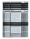
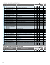
Intelligent output terminalsAnalog monitoring
Intelligent input terminals
Terminal (1) active state
Terminal (2) active state
Terminal (3) active state
Terminal (4) active state
Terminal (5) active state
Terminal (6) active state
Terminal (7) active state
Terminal (8) active state
Terminal FW active state
FM signal selection
AM signal selection
AMI signal selection
C011
C012
C013
C014
C015
C016
C017
C018
C019
C027
C028
C029
00 (RUN: running), 01 (FA1: constant-speed reached), 02 (FA2: set frequency overreached), 03 (OL:
overload notice advance signal (1)), 04 (OD: output deviation for PID control), 05 (AL: alarm signal),
06 (FA3: set frequency reached), 07 (OTQ: over-torque), 08 (IP: instantaneous power failure), 09 (UV:
undervoltage), 10 (TRQ: torque limited), 11 (RNT: operation time over), 12 (ONT: plug-in time over),
13 (THM: thermal alarm signal), 19 (BRK: brake release), 20 (BER: braking error), 21 (ZS: 0 Hz
detection signal), 22 (DSE: speed deviation maximum), 23 (POK: positioning completed),
24 (FA4: set frequency overreached 2), 25 (FA5: set frequency reached 2), 26 (OL2: overload notice
advance signal (2)), 27 (Odc: Analog O disconnection detection), 28 (OIDc: Analog OI disconnection
detection), 29 (O2Dc: Analog O2 disconnection detection), 31 (FBV: PID feedback comparison),
32 (NDc: communication line disconnection), 33 (LOG1: logical operation result 1), 34 (LOG2: logical
operation result 2), 35 (LOG3: logical operation result 3), 36 (LOG4: logical operation result 4),
37 (LOG5: logical operation result 5), 38 (LOG6: logical operation result 6), 39 (WAC: capacitor life
warning)(*2), 40 (WAF: cooling-fan speed drop), 41 (FR: starting contact signal), 42 (OHF: heat sink
overheat warning), 43 (LOC: low-current indication signal), 44 (M01: general-purpose output 1),
45 (M02: general-purpose output 2), 46 (M03: general-purpose output 3), 47 (M04: general-purpose
output 4), 48 (M05: general-purpose output 5), 49 (M06: general-purpose output 6), 50 (IRDY: inverter
ready), 51 (FWR: forward rotation), 52 (RVR: reverse rotation), 53 (MJA: major failure), 54(WCO:
window comparator O), 55(WCOI: window comparator OI), 56 (WCO2: window comparator O2)
(When alarm code output is selected for "C062", functions "AC0" to "AC2" or "AC0" to
"AC3" [ACn: alarm code output] are forcibly assigned to intelligent output terminals 11 to 13
or 11 to 14, respectively.)
00 (output frequency), 01 (output current), 02 (output torque), 03 (digital output frequency), 04 (output
voltage), 05 (input power), 06 (electronic thermal overload), 07 (LAD frequency), 08 (digital current
monitoring), 09 (motor temperature), 10 (heat sink temperature), 12 (general-purpose output YA0)
00 (output frequency), 01 (output current), 02 (output torque), 04 (output voltage), 05 (input power), 06
(electronic thermal overload), 07 (LAD frequency), 09 (motor temperature), 10 (heat sink temperature), 11
(output torque [signed value]), 13 (general-purpose output YA1)
00 (output frequency), 01 (output current), 02 (output torque), 04 (output voltage), 05 (input power), 06
(electronic thermal overload), 07 (LAD frequency), 09 (motor temperature), 10 (heat sink temperature), 14
(general-purpose output YA2)
Intelligent input terminals
01 (RV: Reverse RUN), 02 (CF1: Multispeed 1 setting), 03 (CF2: Multispeed 2 setting),
04 (CF3: Multispeed 3 setting), 05 (CF4: Multispeed 4 setting), 06 (JG: Jogging), 07 (DB:
external DC braking), 08 (SET: Set 2nd motor data), 09 (2CH: 2-stage
acceleration/deceleration), 11 (FRS: free-run stop), 12 (EXT: external trip), 13 (USP:
unattended start protection), 14: (CS: commercial power source enable), 15 (SFT: software
lock), 16 (AT: analog input voltage/current select), 17 (SET3: 3rd motor control), 18 (RS:
reset), 20 (STA: starting by 3-wire input), 21 (STP: stopping by 3-wire input), 22 (F/R:
forward/reverse switching by 3-wire input), 23 (PID: PID disable), 24 (PIDC: PID reset),
26 (CAS: control gain setting), 27 (UP: remote control UP function), 28 (DWN: remote
control DOWN function), 29 (DWN: remote control data clearing), 31 (OPE: forcible
operation), 32 (SF1: multispeed bit 1), 33 (SF2: multispeed bit 2), 34 (SF3: multispeed bit
3), 35 (SF4: multispeed bit 4), 36 (SF5: multispeed bit 5), 37 (SF6: multispeed bit 6),
38 (SF7: multispeed bit 7), 39 (OLR: overload restriction selection), 40 (TL: torque limit
enable), 41 (TRQ1: torque limit selection bit 1), 42 (TRQ2: torque limit selection bit 2),
43 (PPI: P/PI mode selection), 44 (BOK: braking confirmation), 45 (ORT: orientation), 46
(LAC: LAD cancellation), 47 (PCLR: clearance of position deviation), 48 (STAT: pulse train
position command input enable), 50 (ADD: trigger for frequency addition [A145]), 51 (F-TM:
forcible-terminal operation), 52 (ATR: permission of torque command input), 53 (KHC:
cumulative power clearance), 54 (SON: servo-on),
55 (FOC: pre-excitation), 56 (MI1: general-purpose input 1), 57 (MI2: general-purpose input
2), 58 (MI3: general-purpose input 3), 59 (MI4: general-purpose input 4), 60 (MI5:
general-purpose input 5), 61 (MI6: general-purpose input 6), 62 (MI7: general-purpose input 7),
63 (MI8: general-purpose input 8), 64 (EMR: Emergency stop)(*1), 65 (AHD: analog command
holding), 66 (CP1: multistage position settings selection 1 ), 67 (CP2: multistage position
settings selection 2), 68 (CP3: multistage position settings selection 3), 69 (ORL: Zero-return
limit function), 70 (ORG: Zero-return trigger function), 71 (FOT: forward drive stop), 72 (ROT:
reverse drive stop), 73 (SPD: speed / position switching), 74 (PCNT: pulse counter), 75 (PCC:
pulse counter clear), no (NO: no assignment)
00(NO) / 01(NC)
00(NO) / 01(NC)
00(NO) / 01(NC)
00(NO) / 01(NC)
00(NO) / 01(NC)
00(NO) / 01(NC)
00(NO) / 01(NC)
00(NO) / 01(NC)
00(NO) / 01(NC)
Terminal [1] function (*1)
Terminal [2] function
Terminal [3] function (*1)
Terminal [4] function
Terminal [5] function
Terminal [6] function
Terminal [7] function
Terminal [8] function
C001
C002
C003
C004
C005
C006
C007
C008
Terminal (11) function
Terminal (12) function
Terminal (13) function
Terminal (14) function
Terminal (15) function
Alarm relay terminal function
C021
C022
C023
C024
C025
C026
01(FA1)
00(RUN)
03(OL)
07(OTO)
40(WAF)
05(AL)
01(FA1)
00(RUN)
03(OL)
07(OTO)
40(WAF)
05(AL)
01(FA1)
00(RUN)
03(OL)
07(OTO)
40(WAF)
05(AL)
01(FA1)
00(RUN)
03(OL)
07(OTO)
40(WAF)
05(AL)
(*1) When the emergency stop function is enabled (SW1 = ON), "18" (RS) and "64" (EMR) are forcibly written to parameters "C001" and "C003",
respectively. (You cannot arbitrarily write "64" to "C001".) If the SW1 signal is turned off and then turned on, "no" (no assignment) is set in parameter "C003".
(*2) 1850HF,2200HF,3150HF and 4000HF:The function is not provided.
18(RS)
16(AT)
06(JG)
11(FRS)
09(2CH)
03(CF2)
02(CF1)
01(RV)
18(RS)
16(AT)
06(JG)
11(FRS)
09(2CH)
13(USP)
02(CF1)
01(RV)
18(RS)
16(AT)
06(JG)
11(FRS)
09(2CH)
03(CF2)
02(CF1)
01(RV)
18(RS)
16(AT)
06(JG)
11(FRS)
09(2CH)
03(CF2)
02(CF1)
01(RV)
00
00
00
00
00
00
00
00
00
00
00
00
00
00
00
00
00
01
00
00
00
00
00
00
00
00
00
00
00
00
00
00
00
00
00
00
00
00
00
00
00
00
00
00
00
00
00
00
0.
0.0
00
0.00
0.00
0.00
0.00
0.00
0.00
00
380/760
1.00
0.50
0.060
0.
0.0
00
0.00
0.00
0.00
0.00
0.00
0.00
00
380/760
1.00
0.50
0.060
0.
0.0
00
0.00
0.00
0.00
0.00
0.00
0.00
00
380/760
1.00
0.50
0.060
0.
0.0
0.0
0.00
0.00
0.00
0.00
0.00
0.00
00
380/760
1.00
0.50
0.060
Free-setting V/f frequency (7)
Free-setting V/f voltage (7)
Brake control enable
Brake wait time for release
Brake wait time for acceleration
Brake wait time for stopping
Brake wait time for confirmation
Brake release frequency setting
Brake release current setting
Braking frequency
Overvoltage suppression enable
Overvoltage suppression level
Overvoltage suppression propotional gain
Overvoltage suppression Integral time
Acceleration and deceleration rate
at overvoltage suppression
b112
b113
b120
b121
b122
b123
b124
b125
b126
b127
b130
b131
b132
b133
b134
0.0 to 400.0 (Hz) (*1)
0.0 to 800.0 (V)
00 (disabling), 01 (enabling)
0.00 to 5.00 (s)
0.00 to 5.00 (s)
0.00 to 5.00 (s)
0.00 to 5.00 (s)
0.00 to 99.99, 100.0 to 400.0 (Hz) (*2)
0.0 to 2.00 x "rated current"
0.00 to 99.99, 100.0 to 400.0 (Hz) (*2)
00 (disabling the restraint), 01 (decelerating and stagnating), 02 (enabling acceleration)
330 to 390 (V) (200 V class model), 660 to 780 (V) (400 V class model)
0.10 to 30.00 (s)
0.00 to 2.55
0.000 to 9.999 / 10.00 to 63.53 (s)
C GROUP: INTELLIGENT TERMINAL FUNCTIONS
Code
Function Name
Default Setting
-FE(CE) -FU(UL)
SJ700
SJ700B
-F(JP)
Change
during operation
(allowed or not)
Setting
during operation
(allowed or not)
Monitored data or setting
= Allowed = Not permitted
Code
Function Name
Default Setting
-FE(CE) -FU(UL)
SJ700
SJ700B
-F(JP)
Change
during operation
(allowed or not)
Setting
during operation
(allowed or not)
Monitored data or setting
= Allowed = Not permitted
Rated current x 1.00
*
)
Not available
(*1) 4000HF: 0.0 to 120.0(Hz) (*2)4000HF: 0.00 to 99.99, 100.0 to 120.0(Hz)
15
16