


Terminal
Adjustment
Output terminal operation function
Meter adjustment
Levels and output terminal statusCommunication functionAdjustmentOthers
Intelligent
output terminals
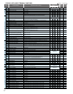
Digital current monitor reference value
Terminal (11) active state
Terminal (12) active state
Terminal (13) active state
Terminal (14) active state
Terminal (15) active state
Alarm relay terminal active state
Low-current indication signal output mode selection
Low-current indication signal detection level
Overload signal output mode
Overload level setting
Frequency arrival setting for accel.
Frequency arrival setting for decel.
PID deviation level setting
Frequency arrival setting for acceleration (2)
Frequency arrival setting for deceleration (2)
Maximum PID feedback data
Minimum PID feedback data
Over-torque(Forward-driving) level setting
Over-torque(Reverse-regenerating) level setting
Over-torque(Reverse-driving) level setting
Over-torque(Forward-regenerating) level setting
Electronic thermal warning level setting
Alarm code input
Zero speed detection level
Heat sink overheat warning level
Communication speed selection
Node allocation
Communication data length selection
Communication parity selection
Communication stop bit selection
Selection of the operation after communication error
Communication timeout limit before tripping
Communication wait time
Communication mode selection
O input span calibration
OI input span calibration
O2 input span calibration
Thermistor input tuning
Debug mode enable
UP/DOWN memory mode selection
Reset mode selection
Restart mode after reset
FM gain adjustment
AM gain adjustment
AMI gain adjustment
AM bias adjustment
AMI bias adjustment
Overload setting (2)
O input zero calibration
OI input zero calibration
O2 input zero calibration
Output 11 on-delay time
Output 11 off-delay time
Output 12 on-delay time
Output 12 off-delay time
Output 13 on-delay time
Output 13 off-delay time
Output 14 on-delay time
Output 14 off-delay time
Output 15 on-delay time
Output 15 off-delay time
Output RY on-delay time
Output RY off-delay time
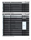
Logical output signal 1 selection 1
Logical output signal 1 selection 2
Logical output signal 1 operator selection
Logical output signal 2 selection 1
Logical output signal 2 selection 2
Logical output signal 2 operator selection
Logical output signal 3 selection 1
C030
C031
C032
C033
C034
C035
C036
C038
C039
C040
C041
C042
C043
C044
C045
C046
C052
C053
C055
C056
C057
C058
C061
C062
C063
C064
C071
C072
C073
C074
C075
C076
C077
C078
C079
C081
C082
C083
C085
C091
C101
C102
C103
C105
C106
C107
C109
C110
C111
C121
C122
C123
C130
C131
C132
C133
C134
C135
C136
C137
C138
C139
C140
C141
C142
C143
C144
C145
C146
C147
C148
00(NO) / 01(NC)
00(NO) / 01(NC)
00(NO) / 01(NC)
00(NO) / 01(NC)
00(NO) / 01(NC)
00(NO) / 01(NC)
SJ700:0.0 to 2.00 x "rated current" (A) / SJ700B:0.0 to 1.50 x "rated current" (A)
SJ700:0.0 to 2.00 x "rated current" (A) / SJ700B:0.0 to 1.50 x "rated current" (A)
0.00 to 99.99, 100.0 to 400.0 (Hz) (*1)
0.00 to 99.99, 100.0 to 400.0 (Hz) (*1)
0.0 to 100.0 (%)
0.00 to 99.99, 100.0 to 400.0 (Hz) (*1)
0.00 to 99.99, 100.0 to 400.0 (Hz) (*1)
0.0 to 100.0 (%)
0.0 to 100.0 (%)
0. to 100. (%)
00(Disabled) / 01(3-bit) / 02(4-bit)
0.00 to 99.99, 100.0 (Hz)
0. to 200.0 ( )
02 (loopback test), 03 (2,400 bps), 04 (4,800 bps), 05 (9,600 bps), 06 (19,200 bps)
1. to 32.
7 (7 bits), 8 (8 bits)
00 (no parity), 01 (even parity), 02 (odd parity)
1 (1 bit), 2 (2 bits)
0.00 to 99.99 (s)
0. to 1000. (ms)
00(ASCII), 01(Modbus-RTU)
0. to 9999., 1000 to 6553(10000 to 65530)
0. to 9999., 1000 to 6553(10000 65530)
0. to 9999., 1000 to 6553(10000 65530)
0.0 to 999.9, 1000.
(Do not change this parameter, which is intended for factory adjustment.)
00 (not storing the frequency data), 01 (storing the frequency data)
50. to 200. (%)
50. to 200. (%)
50. to 200. (%)
0. to 100. (%)
0. to 100. (%)
0. to 9999., 1000 to 6553 (10000 to 65530)
0. to 9999., 1000 to 6553 (10000 to 65530)
0. to 9999., 1000 to 6553 (10000 to 65530)
0.0 to 100.0 (s)
0.0 to 100.0 (s)
0.0 to 100.0 (s)
0.0 to 100.0 (s)
0.0 to 100.0 (s)
0.0 to 100.0 (s)
0.0 to 100.0 (s)
0.0 to 100.0 (s)
0.0 to 100.0 (s)
0.0 to 100.0 (s)
0.0 to 100.0 (s)
0.0 to 100.0 (s)
Same as the settings of C021 to C026 (except those of LOG1 to LOG6)
Same as the settings of C021 to C026 (except those of LOG1 to LOG6)
00 (AND), 01 (OR), 02 (XOR)
Same as the settings of C021 to C026 (except those of LOG1 to LOG6)
Same as the settings of C021 to C026 (except those of LOG1 to LOG6)
00 (AND), 01 (OR), 02 (XOR)
Same as the settings of C021 to C026 (except those of LOG1 to LOG6)
00
00
00
00
00
01
01
01
0.00
0.00
3.0
0.00
0.00
100.0
0.0
100.
100.
100.
100.
80.
00
0.00
120.
04
1.
7
00
1
02
0.00
0.
00
00
00
00
00
100.
100.
100.
0.
20.
0.0
0.0
0.0
0.0
0.0
0.0
0.0
0.0
0.0
0.0
0.0
0.0
00
00
00
00
00
00
00
00
00
00
00
00
01
01
01
0.00
0.00
3.0
0.00
0.00
100.0
0.0
100.
100.
100.
100.
80.
00
0.00
120.
04
1.
7
00
1
02
0.00
0.
00
00
00
00
00
100.
100.
100.
0.
20.
0.0
0.0
0.0
0.0
0.0
0.0
0.0
0.0
0.0
0.0
0.0
0.0
00
00
00
00
00
00
00
00
00
00
00
00
01
01
01
0.00
0.00
3.0
0.00
0.00
100.0
0.0
100.
100.
100.
100.
80.
00
0.00
120.
04
1.
7
00
1
02
0.00
0.
00
00
00
00
00
100.
100.
100.
0.
20.
0.0
0.0
0.0
0.0
0.0
0.0
0.0
0.0
0.0
0.0
0.0
0.0
00
00
00
00
00
00
00
00
00
00
00
00
01
01
01
0.00
0.00
3.0
0.00
0.00
100.0
0.0
100.
100.
100.
100.
80.
00
0.00
120.
04
1.
7
00
1
02
0.00
0.
00
00
00
00
00
100.
100.
100.
0.
20.
0.0
0.0
0.0
0.0
0.0
0.0
0.0
0.0
0.0
0.0
0.0
0.0
00
00
00
00
00
00
00
Rated current of
inverterx 1..0
Rated current of
inverterx 1..0
Factory set
Factory set
Rated current of inverterx 1..0
Rated current of inverterx 1..0
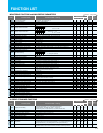
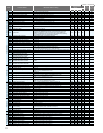
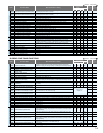
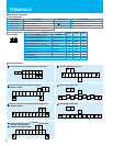
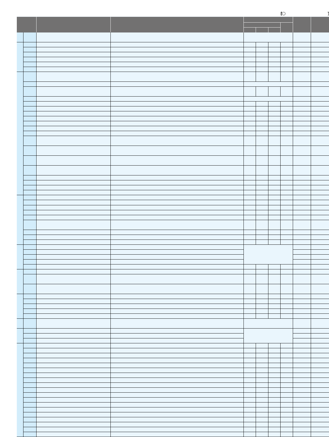
C GROUP: INTELLIGENT TERMINAL FUNCTIONS
SJ700:0.20 x "rated current" to 2.00 x "rated current" (A) / SJ700B:0.20 x "rated current" to 1.50 x "rated current" (A)
(Current with digital current monitor output at 1,440 Hz)
00 (output during acceleration/deceleration and constant-speed operation),
01 (output only during constant-speed operation)
00 (output during acceleration/deceleration and constant-speed operation),
01 (output only during constant-speed operation)
SJ700: 0. to 200. (%) < 75kW and over:0. to 180.>
SJ700B: 0. to 150. (%)
SJ700: 0. to 200. (%) < 75kW and over:0. to 180.>
SJ700B: 0. to 150. (%)
SJ700: 0. to 200. (%) < 75kW and over:0. to 180.>
SJ700B: 0. to 150. (%)
SJ700: 0. to 200. (%) < 75kW and over:0. to 180.>
SJ700B: 0. to 150. (%)
00 (tripping), 01 (tripping after decelerating and stopping the motor), 02 (ignoring errors),
03 (stopping the motor after free-running), 04 (decelerating and stopping the motor)
00 (resetting the trip when RS is on), 01 (resetting the trip when RS is off),
02 (enabling resetting only upon tripping [resetting when RS is on])
00 (starting with 0 Hz), 01 (starting with matching frequency),
02 (restarting with active matching frequency)
Code
Function Name
Default Setting
-FE(CE) -FU(UL)
SJ700
SJ700B
-F(JP)
Change
during operation
(allowed or not)
Setting
during operation
(allowed or not)
Monitored data or setting
= Allowed = Not permitted
SJ700:0.0 to 2.00 x "rated current" (A) <75kW and over:0.0 to 1.80 x "rated current">
SJ700B:0.0 to 1.50 x "rated current" (A)
Analog
monitoring
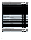
(*1) 1850HF,2200HF,3150HF and 4000HF:0.1 to 999.9,1000. to 6553.(mΩ).
(*2) 1850HF,2200HF,3150HF and 4000HF:0.001 to 9.999,10.00. to 65.53(mH).
(*3) 1850HF,2200HF,3150HF and 4000HF:0.01 to 0.35 “ rated current ”(A).
(*1) 4000HF:0.00 to 99.99, 100.0 to 120.0(Hz)
17
18
Logical output signal 3 selection 2
Logical output signal 3 operator selection
Logical output signal 4 selection 1
Logical output signal 4 selection 2
Logical output signal 4 operator selection
Logical output signal 5 selection 1
Logical output signal 5 selection 2
Logical output signal 5 operator selection
Logical output signal 6 selection 1
Logical output signal 6 selection 2
Logical output signal 6 operator selection
Input terminal response time setting 1
Input terminal response time setting 2
Input terminal response time setting 3
Input terminal response time setting 4
Input terminal response time setting 5
Input terminal response time setting 6
Input terminal response time setting 7
Input terminal response time setting 8
Input terminal response time setting FW
Multistage speed/position determination time
Same as the settings of C021 to C026 (except those of LOG1 to LOG6)
00 (AND), 01 (OR), 02 (XOR)
Same as the settings of C021 to C026 (except those of LOG1 to LOG6)
Same as the settings of C021 to C026 (except those of LOG1 to LOG6)
00 (AND), 01 (OR), 02 (XOR)
Same as the settings of C021 to C026 (except those of LOG1 to LOG6)
Same as the settings of C021 to C026 (except those of LOG1 to LOG6)
00 (AND), 01 (OR), 02 (XOR)
Same as the settings of C021 to C026 (except those of LOG1 to LOG6)
Same as the settings of C021 to C026 (except those of LOG1 to LOG6)
00 (AND), 01 (OR), 02 (XOR)
0. to 200. ( 2ms)
0. to 200. ( 2ms)
0. to 200. ( 2ms)
0. to 200. ( 2ms)
0. to 200. ( 2ms)
0. to 200. ( 2ms)
0. to 200. ( 2ms)
0. to 200. ( 2ms)
0. to 200. ( 2ms)
0. to 200. ( 10ms)
other
C149
C150
C151
C152
C153
C154
C155
C156
C157
C158
C159
C160
C161
C162
C163
C164
C165
C166
C167
C168
C169
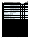
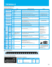
Output terminal operation function
Input terminal response
Auto-tuning Setting
Motor data selection, 1st motor
Motor data selection, 2nd motor
Motor capacity, 1st motor
Motor capacity, 2nd motor
Motor poles setting, 1st motor
Motor poles setting, 2nd motor
Motor speed constant, 1st motor
Motor speed constant, 2nd motor
Motor stabilization constant, 1st motor
Motor stabilization constant, 2nd motor
Motor stabilization constant, 3rd motor
Motor constant R1, 1st motor
Motor constant R1, 2nd motor
Motor constant R2, 1st motor
Motor constant R2, 2nd motor
Motor constant L, 1st motor
Motor constant L, 2nd motor
Motor constant Io
Motor constant Io, 2nd motor
Motor constant J
Motor constant J, 2nd motor
Auto constant R1, 1st motor
Auto constant R1, 2nd motor
Auto constant R2, 1st motor
Auto constant R2, 2nd motor
Auto constant L, 1st motor
Auto constant L, 2nd motor
Auto constant Io, 1st motor
Auto constant Io, 2nd motor
Auto constant J, 1st motor
Auto constant J, 2nd motor
PI proportional gain for 1st motor
PI proportional gain for 2nd motor
PI integral gain for 1st motor
PI integral gain for 2nd motor
P proportional gain setting for 1st motor
P proportional gain setting for 2nd motor
Zero LV lmit for 1st motor
Zero LV lmit for 2nd motor
Zero LV starting boost current for 1st motor
Zero LV starting boost current for 2nd motor
Terminal selection PI proportional gain setting
Terminal selection PI integral gain setting
Terminal selection P proportional gain setting
Gain switching time
SJ700:0.20 to 400.0 (kW)/SJ700B:0.20 to 160(kW)
SJ700:0.20 to 400.0 (kW)/SJ700B:0.20 to 160(kW)
2, 4, 6, 8, 10 (poles)
2, 4, 6, 8, 10 (poles)
0.001 to 9.999, 10.00 to 80.00 (10.000 to 80.000)
0.001 to 9.999, 10.00 to 80.00 (10.000 to 80.000)
0. to 255.
0. to 255.
0. to 255.
0.001 to 9.999, 10.00 to 65.53 (Ω) (*1)
0.001 to 9.999, 10.00 to 65.53 (Ω) (*1)
0.001 to 9.999, 10.00 to 65.53 (Ω) (*1)
0.001 to 9.999, 10.00 to 65.53 (Ω) (*1)
0.01 to 99.99, 100.0 to 655.3 (mH) (*2)
0.01 to 99.99, 100.0 to 655.3 (mH) (*2)
0.01 to 99.99, 100.0 to 655.3 (A) (*3)
0.01 to 99.99, 100.0 to 655.3 (A) (*3)
0.001 to 9.999, 10.00 to 99.99, 100.0 to 999.9, 1000. to 9999.
0.001 to 9.999, 10.00 to 99.99, 100.0 to 999.9, 1000. to 9999.
0.001 to 9.999, 10.00 to 65.53 (Ω) (*1)
0.001 to 9.999, 10.00 to 65.53 (Ω) (*1)
0.001 to 9.999, 10.00 to 65.53 (Ω) (*1)
0.001 to 9.999, 10.00 to 65.53 (Ω) (*1)
0.01 to 99.99, 100.0 to 655.3 (mH) (*2)
0.01 to 99.99, 100.0 to 655.3 (mH) (*2)
0.01 to 99.99, 100.0 to 655.3 (A) (*3)
0.01 to 99.99, 100.0 to 655.3 (A) (*3)
0.001 to 9.999, 10.00 to 99.99, 100.0 to 999.9, 1000. to 9999.
0.001 to 9.999, 10.00 to 99.99, 100.0 to 999.9, 1000. to 9999.
0.0 to 999.9, 1000.
0.0 to 999.9, 1000.
0.0 to 999.9, 1000.
0.0 to 999.9, 1000.
0.01 to 10.00
0.01 to 10.00
0.0 to 100.0
0.0 to 100.0
0. to 50. (%)
0. to 50. (%)
0.0 to 999.9, 1000.
0.0 to 999.9, 1000.
0.00 to 10.00
0. to 9999. (ms)
H001
H002
H202
H003
H203
H004
H204
H005
H205
H006
H206
H306
H020
H220
H021
H221
H022
H222
H023
H223
H024
H224
H030
H230
H031
H231
H032
H232
H033
H233
H034
H234
H050
H250
H051
H251
H052
H252
H060
H260
H061
H261
H070
H071
H072
H073
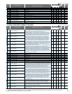
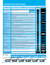
Control constants
Control constants
H GROUP: MOTOR CONSTANTS FUNCTIONS
00
00
00
00
00
00
00
00
00
00
00
1
1
1
1
1
1
1
1
1
0
00
00
00
4
4
1,590
1,590
100.
100.
100.
00
00
00
4
4
1,590
1,590
100.
100.
100.
00
00
00
4
4
1,590
1,590
100.
100.
100.
00
00
00
00
00
00
00
00
00
00
00
1
1
1
1
1
1
1
1
1
0
00
00
00
00
00
00
00
00
00
00
00
1
1
1
1
1
1
1
1
1
0
00
00
00
4
4
1,590
1,590
100.
100.
100.
00
00
00
00
00
00
00
00
00
00
00
1
1
1
1
1
1
1
1
1
0
Factory set
Depending on
motor capacity
Code
Function Name
Default Setting
-FE(CE) -FU(UL)
SJ700
SJ700B
-F(JP)
Change
during operation
(allowed or not)
Setting
during operation
(allowed or not)
Monitored data or setting
= Allowed = Not permitted
Code
Function Name
Default Setting
-FE(CE) -FU(UL)
SJ700
SJ700B
-F(JP)
Change
during operation
(allowed or not)
Setting
during operation
(allowed or not)
Monitored data or setting
= Allowed = Not permitted
100.0
100.0
100.0
100.0
1.00
1.00
100.
100.
50.
50.
100.0
100.0
1.00
100.
100.0
100.0
100.0
100.0
1.00
1.00
70.
70.
50.
50.
100.0
100.0
1.00
100.
100.0
100.0
100.0
100.0
1.00
1.00
100.
100.
50.
50.
100.0
100.0
1.00
100.
100.0
100.0
100.0
100.0
1.00
1.00
100.
100.
50.
50.
100.0
100.0
1.00
100.
00 (disabling auto-tuning), 01 (auto-tuning without rotation),
02 (auto-tuning with rotation)
00 (Hitachi standard data), 01 (auto-tuned data),
02 (auto-tuned data [with online auto-tuning function])
00 (Hitachi standard data), 01 (auto-tuned data),
02 (auto-tuned data [with online auto-tuning function])
*
)
Not available