


9 D04-991-2400 5/1/04
D/G-04 Maintenance
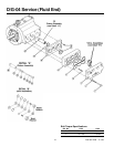
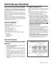
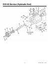
NOTE: The numbers in parentheses are the Ref. Nos. on
the illustrations in the Parts Manual.
Daily
Check the oil level and the condition of the oil. The oil level
should be 1/4 in. (6 mm) above the cast surface in the upper oil
reservoir.
Use the appropriate Hydra-Oil for the application (contact
Wanner Engineering if in doubt).
CAUTION: If you are losing oil but don’t see any external
leakage, or if the oil becomes discolored and contaminated,
one of the diaphragms (17) may be damaged. Refer to the
Fluid-End Service Section. Do not operate the pump with a
damaged diaphragm.
CAUTION: Do not leave contaminated oil in the pump
housing or leave the housing empty. Remove contaminated
oil as soon as discovered, and replace it with clean oil.
Periodically
Change the oil after the first 100 hours of operation, then change
according to the quidelines below. When changing, remove the
drain plug (60) at the bottom of the pump so all oil and
accumulated sediment will drain out.
Hours Between Oil Changes @ Various
Process Fluid Temperatures
<90°F <139°F<180°F
Pressure RPM (32°C) (60°C) (82°C)
<1500 psi (100 bar) <1200 6,000 4,000 2,000
<1800 3,000 2,000 1,500
<2500 psi (170 bar) <1200 3,000 2,000 1,500
<1800 1,500 — 1,000
NOTE: Minimum oil viscosity for proper hydraulic end
lubrication is 16-20 cST (80-100 SSU).
NOTE: Use of an oil cooler is recommended when process
fluid and/or hydraulic end oil exceeds 180
°F (82°C).
CAUTION: Do not turn the drive shaft while the oil reservoir
is empty.
Check the inlet pressure or vacuum periodically with a gauge.
If vacuum at the pump inlet exceeds 7 in. Hg (180 mm Hg),
check the inlet piping system for blockages. If the pump inlet is
located above the supply tank, check the fluid supply level and
replenish if too low.
CAUTION: Protect the pump from freezing. Refer also to
the “Shutdown Procedure”.
Shutdown Procedure During
Freezing Temperatures
Take all safety precautions to assure safe handling of the
fluid being pumped. Provide adequate catch basins for fluid
drainage and use appropriate plumbing from drain ports,
etc., when flushing the pump and system with a compatible
antifreeze.
1. Adjust the discharge pressure regulating valve so the pump
runs under minimum pressure. Stop the pump.
2. Drain supply tank; open any draincocks in system piping
and collect drainage. Drain as much fluid from the pump
manifold and plumbing attached directly to the pump
manifold by loosening fittings or removing plugs or gauges.
3. Close draincocks in system piping and tighten or replace
any fittings, gauges or plugs.
4. Fill supply tank with enough antifreeze to fill system piping
and pump.
NOTE: Disconnect the system return line from the
supply tank and connect it to a separate reservoir.
5. Start the pump and allow it to run until the system is filled
with antifreeze. NOTE: If the system has an airlock and
the pump fails to prime, follow step 4 of the Initial Start-
up Procedure to clear the air.
6. When mostly antifreeze is flowing from the system return
line, stop the pump. Connect the system return line back to
the supply tank and circulate the antifreeze for a short period.
7. It is also good practice to change the oil in the hydraulic end
before storage for an extended period. This will remove any
accumulated condensation and sediment from the oil
reservoir. Drain and refill the hydraulic end with the
appropriate Hydra-Oil and operate the pump for a short
period to assure smooth performance.