


6 D04-991-2400 5/1/04
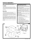
D/G-04 Installation
Inlet Calculations
Acceleration Head
Calculating the Acceleration Head
Use the following formula to calculate acceleration head losses.
Subtract this figure from the NPSHa, and compare the result to
the NPSHr of the Hydra-Cell pump.
Ha = (L x V x N x C) ÷ (K x G)
where:
Ha = Acceleration head (ft of liquid)
L= Actual length of suction line (ft) — not equivalent length
V= Velocity of liquid in suction line (ft/sec) [V = GPM x (0.408 ÷
pipe ID
2
)]
N=RPM of crank shaft
C=Constant determined by type of pump — use 0.066 for the
D-04 and G-04 Hydra-Cell pumps
K= Constant to compensate for compressibility of the fluid —
use: 1.4 for de-aerated or hot water; 1.5 for most liquids;
2.5 for hydrocarbons with high compressibility
G=Gravitational constant (32.2 ft/sec
2
)
Inlet Piping (Suction Feed)
CAUTION: When pumping at temperatures above 160° F
(71
° C), use a pressure-feed system.
Install draincocks at any low points of the suction line, to permit
draining in freezing conditions.
Provide for permanent or temporary installation of a vacuum
gauge to monitor the inlet suction. To maintain maximum flow,
vacuum at the pump inlet should not exceed 7 in. Hg at 3 gpm
and 70° F (180 mm Hg at 11.4 liters/min and 21° C). Do not
supply more than one pump from the same inlet line.
Supply Tank
Use a supply tank that is large enough to provide time for any
trapped air in the fluid to escape. The tank size should be at
least twice the maximum pump flow rate.
Isolate the pump and motor stand from the supply tank, and
support them separately.
Install a separate inlet line from the supply tank to each pump.
Install the inlet and bypass lines so they empty into the supply
tank below the lowest water level, on the opposite side of the
baffle from the pump suction line.
If a line strainer is used in the system install it in the inlet line to
the supply tank.
To reduce aeration and turbulence, install a completely
submerged baffle plate to separate the incoming and outgoing
liquids.
Install a vortex breaker in the supply tank, over the outlet port
to the pump.
Place a cover over the supply tank, to prevent foreign objects
from falling into it.
Hose Size and Routing
Use the shortest, most-direct route from the supply tank to the
pump. If elbows are needed, 45° are recommended. Any
restrictions in the inlet piping may cause pump output to drop.
Do not install any 90
° elbows in the pump inlet.
• Use flexible noncollapsible hose between the pump and rigid
piping or supply tank. This will absorb vibration, and allow
for expansion or contraction.
• Use the largest practical hose. The smallest permissible size
is 5/8 in. (16 mm) I.D.
• All valves, fittings, and unions must also have 5/8-in. (16
mm) minimum I.D. Do not exceed 5 feet of hose and piping
between and supply tank and the pump inlet.
• Support the pump and piping independently.
• Make sure all joints are sealed and tight, to prevent the pump
from drawing air into the inlet.
• Do not use a line strainer or filter in the suction line unless
regular maintenance is assured. If used, it should have a
free-flow area of at least three times the free-flow area of
the inlet.
Loctite is a registered trademark of Loctite Corporation.
Teflon is a registered trademark of E. I. DuPont de Nemours & Co. Inc.
Inlet Piping (Pressure Feed)
Provide for permanent or temporary installation of a vacuum/
pressure gauge to monitor the inlet vacuum or pressure.
Pressure at the pump inlet should not exceed 500 psi (34 bar);
if it could get higher, install an inlet pressure regulator.
Do not supply more than one pump from the same inlet line.