


11 D04-991-2400 5/1/04
D/G-04 Service (Fluid End)
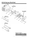
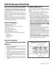
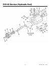
NOTE: The number in parentheses are the Reference
numbers on the illustration at right and in the Parts Manual.
This section explains how to disassemble and inspect all easily
serviceable parts of the pump. Repair procedures for the
hydraulic end (oil reservoir) of the pump are included in a later
section of the manual.
CAUTION: Do not disassemble the hydraulic end unless you
are a skilled mechanic. For assistance, contact Wanner
Engineering (TEL 612-332-5681 or FAX 612-332-6937) or the
distributor in your area.
CAUTION: The two capscrews (16) that screw through the
diaphragm plate in the pump housing hold the diaphragm plate
over the hydraulic end of the pump. Do not remove them except
when repairing the hydraulic end.
Tools and Supplies
• Straightedge (at least 6 in. long)
• Grease or petroleum jelly
• Torque wrench, rated to at least 50 ft-lbs (70 N-m)
• Emery cloth
• 1/2-in. drive socket wrench
• 5/16-in. (8-mm) open-end wrench
• 5-mm hex Allen wrench
• 8-mm hex bit socket (1/2 inch drive)
• Wanner D-04/G-04 Tool Kit, which includes the following:
• Seat puller
• Plunger holder
• Plunger guide lifter
• Shaft rotator
Service Procedures
1. Remove Manifold (3) and Valve
Plate (12)
a. Remove all eight capscrews (1) around the manifold.
Use an 8-mm hex Allen wrench.
b. Remove the manifold (3).
c. Inspect the manifold for warping or wear around the inlet
and outlet ports. If wear is excessive, replace the
manifold.
To check if the manifold is warped, place a straightedge
across it. A warped manifold should be replaced.
d. Remove the two socket-head capscrews (14) that hold
the valve plate to the pump housing. Use a 5-mm hex
Allen wrench.
e. Inspect the valve plate in the same manner as the
manifold, for excessive wear and/or warping. Replace if
necessary.
2. Inspect Valves (5-11)
The three inlet and three outlet valve assemblies are identical
(but face in opposite directions). Inspect each valve as
follows:
a. Check the spring retainer (10), and replace if worn.
b. Check the valve spring (8). If shorter than a new spring,
replace it (do not stretch a used spring).
c. Check the valve (7). If worn excessively, replace it.
d. Remove the valve seat (6), O-ring (5), and dampening
washer (11) (See note below). A seat puller is included
in the Wanner Tool Kit. Inspect all parts for wear. In all
instances, O-ring (5) should be replaced. Replace the
valve seat and/or dampening washer if necessary.
NOTE: On newer pump models, the dampening
washer (11) is not used because the valve seat (6) is
thicker. When replacing the valve seat on an older
pump model which has dampening washers, do
not
reinstall the dampening washers as the new valve
seat is thicker than the original.
e. Reinstall the valve assemblies:
• Clean the valve ports and shoulders with emery cloth,
and lubricate them with lubricating gel or petroleum jelly.
• Install the O-ring (5) on the valve seat (6).
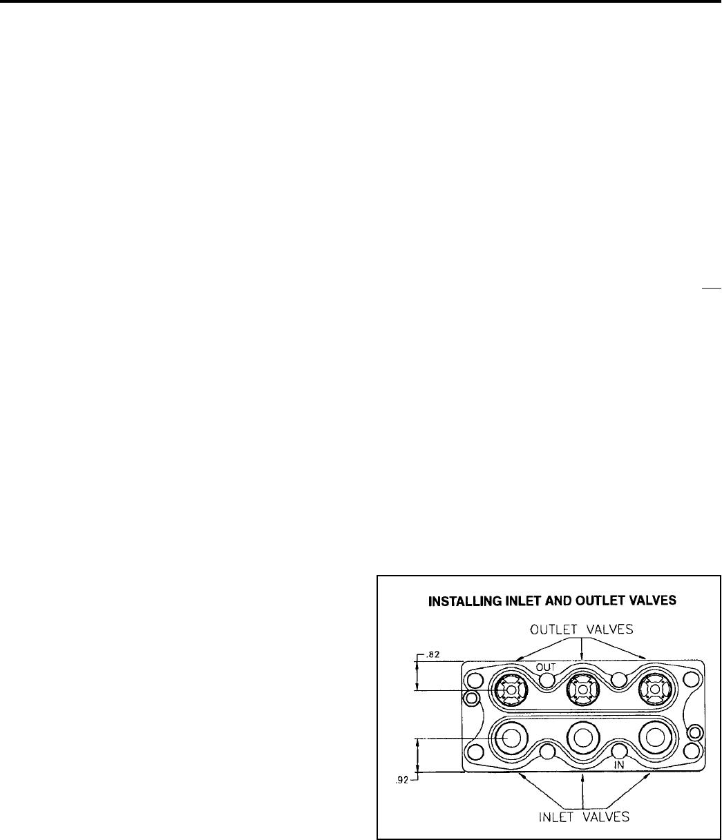
• Inlet (3 lower valves in the illustration below). Insert
the spring retainer (10) into the valve plate, then insert
the spring, valve, Tetra seal, valve seat, and dampening
washer (8,7,9,6,11). A flat O-ring (Tetra seal, 9) goes
between the retainer and seat.
• Outlet (3 upper valves in the illustration below).
Insert the dampening washer, valve seat, Tetra seal,
valve, and spring, then the retainer. Install the flat O-ring
(Tetra seal, 9) between the retainer and seat.