


8 D04-991-2400 5/1/04
Before Initial Start-Up
Before you start the pump, be sure that:
• All shutoff valves are open, and the pump has an adequate
supply of fluid.
• All connections are tight.
• The oil level is 1/4 inch (6 mm) above the cast surface in
the upper oil reservoir.
• The relief valve on the pump outlet is adjusted so the pump
starts under minimum pressure.
• All pulleys and belts are properly aligned, and belts are
tensioned according to specification.
• All pulleys and belts have adequate safety guards.
Initial Start-Up Procedure
1. Turn on power to the pump motor.
2. Check the inlet pressure or vacuum. To maintain maximum
flow, inlet vacuum must not exceed 7 in. Hg at 70° F (180
mm Hg at 21° C). Inlet pressure must not exceed 500 psi
(34 bar).
3. Listen for any erratic noise, and look for unsteady flow. If
the pump does not clear, refer to the Trouble-shooting
Section.
4. If the system has an air lock and the pump fails to prime:
a. Turn off the power.
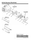
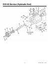
b. Remove the pressure gauge or plug from the tee fitting
at the pump outlet (refer to the illustration on page 3).
NOTE: Fluid may come out of this port when the plug
is removed. Provide an adequate catch basin for fluid
spillage, if required. Fluid will come out of this port when
the pump is started, so we recommend that you attach
adequate plumbing from this port so fluid will not be
sprayed or lost. Use high-pressure-rated hose and
fittings from this port. Take all safety precautions to
assure safe handling of the fluid being pumped.
c. Jog the system on and off until the fluid coming from
this port is air-free.
d. Turn off the power.
e. Remove the plumbing that was temporarily installed,
and reinstall the pressure gauge or plug.
5. Adjust the discharge pressure regulator to the desired
operating and bypass pressures. Do not exceed the
maximum pressure rating of the pump.
6. After the pressure regulator is adjusted, set the “pop-off”
safety relief valve at 100 psi (7 bar) higher than the desired
operating pressure. To verify this setting, adjust the
discharge pressure regulator upward until the relief valve
opens. Follow the recommendations in the above NOTE
(step 4b) for handling the fluid that will come from the relief
valve.
7. Reset the discharge pressure regulator to the desired system
pressure.
8. Provide a return line from the relief valve to the supply tank,
similar to the bypass line from the pressure regulator.
D/G-04 Installation