


7 D04-991-2400 5/1/04
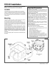
D/G-04 Installation
Discharge Piping
NOTE: Consult the Factory before manifolding two or more
pumps together.
NOTE: Single-acting pumps create a pulsing flow. Using
pulsation dampening devices in the discharge line can
reduce or eliminate this.
Hose and Routing
Use the shortest, most-direct route for the discharge line.
Select pipe or hose with a working pressure rating of at least
1.5 times the maximum system pressure. EXAMPLE: Select a
3000-psi W.P.-rated hose for systems to be operated at 2000-
psi-gauge pressure.
Use about 6 ft (1.8 m) of flexible hose between the pump and
rigid piping.
Support the pump and piping independently.
Pressure Regulation
IInstall a pressure regulator or unloader in the discharge
line. Bypass pressure must not exceed the pressure limit of
the pump.
Size the regulator so that, when fully open, it will be large enough
to relieve the full capacity of the pump without overpressurizing
the system.
Locate the valve as close to the pump as possible and ahead
of any other valves.
Adjust the pressure regulating valve to no more than 10% over
the maximum working pressure of the system. Do not exceed
the manufacturer’s pressure rating for the pump or regulator.
Route the bypass line to the supply tank, or to the suction line
as far as possible from the pump (to reduce the chance of
turbulence and cavitation).
If the pump may be run for a long time with the discharge closed
and fluid bypassing, install a thermal protector in the bypass
line (to prevent severe temperature buildup in the bypassed
fluid).
CAUTION: Never install shutoff valves in the bypass line
or between the pump and pressure regulator or relief valve.
Provide for permanent or temporary installation of a pressure
gauge to monitor the discharge pressure at the pump.
For additional system protection, install a “pop-off” safety relief
valve in the discharge line, downstream from the pressure
regulator.
Friction Losses
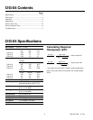
Calculating Friction Losses in Suction Piping
When following the above recommendations (under “inlet
Piping”) for minimum hose/pipe I.D. and maximum length,
frictional losses in the suction piping are negligible (i.e., Hf = 0)
if you are pumping a water-like fluid.
When pumping more-viscous fluids such as lubricating oils,
sealants, adhesives, syrups, varnishes, etc., frictional losses
in the suction piping may become significant. As Hf increases,
the available NPSH (NPSHa) will decrease, and cavitation will
occur.
In general, frictional losses increase with increasing viscosity,
increasing suction-line length, increasing pump flowrate, and
decreasing suction-line diameter. Changes in suction-line
diameter have the greatest impact on frictional losses: a 25%
increase in suction-line diameter cuts losses by more than two
times, and a 50% increase cuts losses by a factor of five times.
Consult the factory before pumping viscous fluids.
Minimizing Acceleration Head and Frictional Losses
To minimize the acceleration head and frictional losses:
• Keep inlet lines less than 3 ft (1 m) long
• Use at least 5/8 in. (16 mm) I.D. inlet hose
• Use soft hose (low-pressure hose, noncollapsing) for the
inlet lines
• Minimize fittings (elbows, valves, tees, etc.)
• Use a suction stabilizer on the inlet.
Net Positive Suction Head
NPSHa must be equal to or greater than NPSHr. If not, the
pressure in the pump inlet will be lower than the vapor pressure
of the fluid— and cavitation will occur.
Calculating the NPSHa
Use the following formula to calculate the NPSHa:
NPSHa = Pt + Hz - Hf - Ha - Pvp
where:
Pt = Atmospheric pressure
Hz = Vertical distance from surface liquid to pump centerline (if
liquid is below pump centerline, the Hz is negative)
Hf = Friction losses in suction piping
Ha = Acceleration head at pump suction
Pvp = Absolute vapor pressure of liquid at pumping temperature
NOTES:
• In good practice, NPSHa should be 2 ft greater than NPSHr
• All values must be expressed in feet of liquid
Atmospheric Pressure at Various Altitudes
Altitude Pressure Altitude Pressure
(ft) (ft of H
2
O) (ft) (ft of H
2
O)
0 33.9 1500 32.1
500 33.3 2000 31.5
1000 32.8 5000 28.2