


Page 6 Installer’s Information Manual
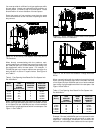
TERMINATION LOCATION AND CLEARANCES
Vent pipe and combustion-air-supply pipe (when direct
vented) may terminate through a roof or through a sidewall.
Roof termination has the advantages of better pipe
protection and fewer condensate-damage concerns. Use
the following guidelines when choosing a vent location:
?? Flue gases can be corrosive. When sidewall venting,
protect walls with a corrosion resistant material. Also,
terminate away from plants and shrubs.
?? Locate termination consistent with the National Fuel
Gas Code, ANSI Z223.1/NFPA 54 or the CAN/CGA
B149 Installation Codes.
?? Locate termination away from other air intake or
exhaust vents such as dryer vents, other gas appliance
vents, or plumbing vents. Allow at least 3 foot to any
other vent.
?? Terminal must not be located above a walkway,
driveway or within 10 feet of an adjacent building.
?? Do not locate termination underneath a veranda,
porch, or deck.
IN THE UNITED STATES:
?? Allow a minimum clearance of 4 feet from electric
meters, gas meters, regulators, and relief equipment.
?? When non-direct venting, terminal must be at least 4
feet below, or 4 feet horizontally from or one foot above
any door, window or gravity air inlet into a building.
Terminal must also be at least 3 feet above any forced-
air inlet located within 10 feet horizontally.
?? When direct venting, vent terminal must be at least one
foot from any opening through which flue gases could
enter a building.
IN CANADA:
?? Allow 6 feet clearance to any mechanical air supply or
service regulator vent and 6 feet horizontally to any gas
meter, electric meter, or relief device.
?? Do not terminate above a meter/regulator assembly
within 3 feet horizontally of the vertical center line of
the regulator
?? Do not terminate within one foot (3 feet for 108,000 and
126,000 Btu models) of a window or door that can be
opened, a non-mechanical-air-supply inlet, or the
combustion-air inlet of any other appliance
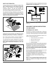
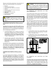
EXISTING VENT CONSIDERATIONS
When a Category I furnace is removed or replaced, the old
venting system may not be properly sized to vent the
remaining appliance(s), for example, a gas water heater.
An improperly sized venting system may promote the
formation of condensate, leakage or spillage.
The following steps shall be followed with each appliance
connected to the old venting system placed in operation,
while any other appliances connected to the venting system
are not in operation:
1. Seal any unused openings in the venting system;
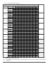
2. Inspect the venting system for proper size and
horizontal pitch, as required in the National Fuel Gas
Code, ANSI Z223.1/NFPA 54 or the CAN/CGA B149
Installation Codes. Determine that there is no
blockage or restriction, leakage, corrosion and other
deficiencies which could cause an unsafe condition;
3. In so far as is practical, close all building doors and
windows and all doors between space in which
appliance(s) connected to the venting system are
located and other spaces of building.
4. Close fireplace dampers.
5. Turn on clothes dryers and any appliance not
connected to the venting system. Turn on any exhaust
fans, such as range hoods and bathroom exhausts, so
they shall operate at maximum speed. Do not operate
a summer exhaust fan.
6. Follow the lighting instructions. Place the appliance
being inspected in operation. Adjust thermostat so
appliance shall operate continuously;
7. Test for drafthood equipped appliance spillage at the
drafthood relief opening after 5 minutes of main burner
operation. Use the flame of a match or candle;
8. After it has been determined that each appliance
connected to the venting system properly vents when
tested as outlined above, return doors, windows,
exhaust fans, fireplace dampers and any other gas-
burning appliance to their previous conditions of use;
9. If improper venting is observed during any of the above
tests, the venting system must be corrected. Follow
the National Fuel Gas Code, ANSI Z223.1/NFPA 54 or
CAN/CGA B149 Installation Codes to correct improper
vent operation. Any "common vent" re-sizing must
approach minimum size determined using current
venting tables.
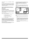
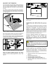
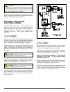
DIRECT OR NON-DIRECT VENTING?
This furnace may be installed using either direct venting or
non-direct venting.
A direct-vented furnace takes all air for combustion directly
into the furnace through a pipe from outdoors. To direct
vent this furnace you must install two pipes to the outdoors.
One pipe supplies combustion air that the furnace needs to
operate. The other pipe vents flue gases to the outdoors.
Use direct venting when indoor air may be contaminated
with chemicals such as chlorine, fluorine, bromine or iodine.
When these chemicals are burned with natural gas or
propane gas, acids are produced that may decrease heat
exchanger life. You should also consider direct venting
when furnace is installed in a space with limited combustion
and ventilation air. See “CONFINED SPACE