


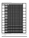
Installer’s Information Manual Page 5
SECTION 4. PROVIDING VENTING
AND COMBUSTION AIR
This furnace must be connected to a plastic venting system
adequate to remove flue gases to the outside atmosphere.
It must be vented in accordance with these instructions and
local building codes.
The furnaces covered by this manual are design-certified
as Category IV appliances. Category IV appliances operate
with a positive vent static pressure and with a flue gas
temperature that will produce significant condensate in the
vent. The vent system for this furnace must be installed so
as to prevent leakage of flue gases into the building. This
furnace may be installed using either direct venting or non-
direct venting.
WARNING: Do not connect this furnace to a vent
system shared by any other appliance. Do not connect it to
any other type of vent system other than described by these
instructions. Improper venting could allow combustion
products to collect in building during use resulting in nausea
or death by asphyxiation.
GENERAL VENTING GUIDELINES
?? Vent system and combustion air supply components
must be constructed of schedule 40 PVC, PVC-DWV,
SDR26, SDR 21 or ABS plastic pipe, fittings, sealants,
and installation procedures that conform to the
following ANSI/ASTM standards:
PVC ASTM D-1785
SDR26, SDR21 ASTM D-2241
PVC-DWV ASTM D-2665
PVC-DWV Cellular Core ASTM F-891
PVC Primer And Solvent Cement ASTM D-2564
ABS Pipe And Fittings ASTM D-2235
Procedure For Cementing Joints ASTM D-2855
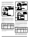
?? All condensate formed in the vent must run back
toward furnace for proper drainage. Install vent pipe
with no less than a 1/4 inch per foot slope from furnace
to vent terminal.
?? Install vent pipe without dips or sags that may hold
water. Support horizontal portions of vent pipe every 5
feet (3 feet for SDR-21 or SDR-26 pipe).
?? Protect vent from freezing. Long runs of vent pipe
installed in an unconditioned space may require
insulation to prevent freezing of condensate.
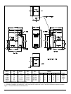
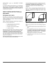
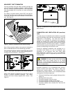
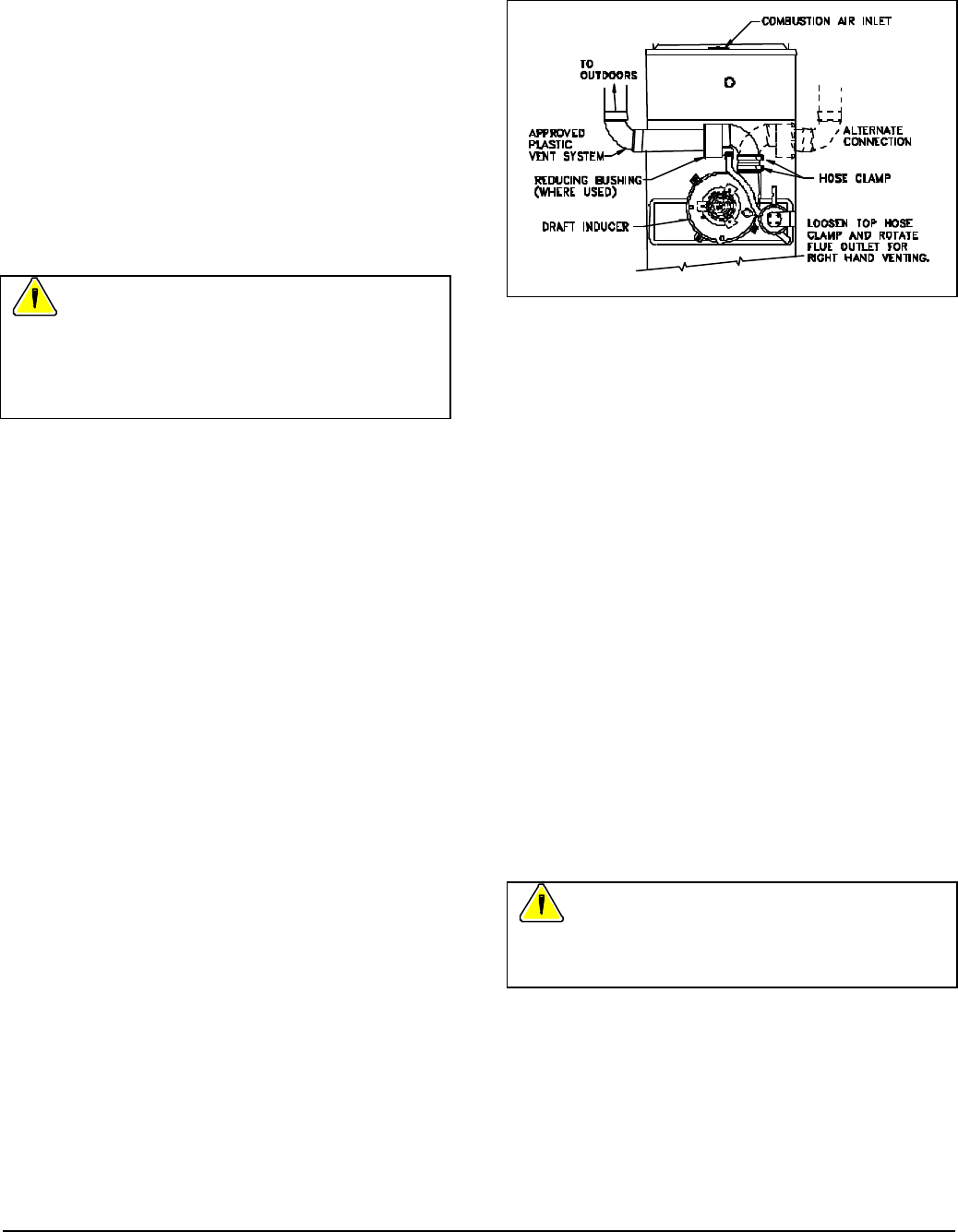
?? Furnace can be vented from either left or right side.
See Figure 2. As shipped, furnace is setup for venting
through the left side. Right side venting is
accomplished by rotating flue outlet fitting and adding a
street elbow to the drain fitting. Street elbow and
instructions are supplied in the furnace parts package.
?? Some models are shipped with a 3-inch to 2-inch
reducer bushing. When venting with two-inch pipe,
install reducer bushing in flue outlet fitting.
Figure 2. Vent Connection to Furnace.
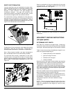
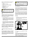
PVC PIPE INSTALLATION INSTRUCTIONS
1. Cut ends of pipe square using a miter box, power saw
or PVC tubing cutter. Put a 10 to 15 degree chamfer
on end of pipe. Remove any burrs, dirt, grease, and
moisture. Check joint for proper fit.
2. Freely coat outside end of pipe and inside of fitting
socket with cleaner-primer. The purpose of the primer
is to dissolve and penetrate the surface of the pipe.
Several coats may be necessary to do this.
3. While primer is still wet, apply a heavy coat of solvent
cement to outside of pipe. Next, using outward strokes
to keep excess cement out of socket, apply a generous
coat of cement to the inside of socket.
4. While both surfaces are still wet with cement, insert
pipe into fitting socket until it bottoms out, using a slight
twisting motion (1/4 turn). Hold pipe in socket 30
seconds to allow cement to set.
5. Allow joint to cure before handling.
Caution: Keep solvent cement container sealed when not
in use. Do not use solvent cement that has thickened or is
gel-like.
WARNING: PVC cements are highly flammable.
Do not use near open flames. A fire or explosion could
result. Avoid prolonged breathing or contact with skin or
eyes.