


Page 18 Installer’s Information Manual
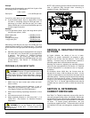
SECTION 9. INSTALLING DUCT
SYSTEM
Properly size duct system based on heat loss and heat gain
calculations to ensure good heating and cooling
installations, potentially fewer call-backs, and delivery of
required circulating air. Install duct system to meet current
Standard for Installations of Warm Air Heating and Air
Systems ASHRAE/NFPA 90 and local codes.
CAUTION: Failure to follow these standards could reduce
airflow or increase air leakage, resulting in reduced system
performance or furnace damage.
Design duct system so furnace will operate at a static
pressure of 0.50 inches W.C. or less. This static pressure
limitation includes the total pressure losses on both supply
air side and return air side of system. Supply side pressure
loss includes cooling coil, ducts and room registers. Return
side pressure loss includes return grilles and ducts.
Pressure losses are calculated based on 400 CFM per ton
of cooling.
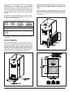
SUPPLY AIR DUCT WORK
Supply air duct (plenum) connections must be at least as
big as furnace supply opening. Seal supply-air ductwork to
furnace casing, walls, ceilings or floors it passes through.
End ductwork outside furnace space.
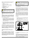
On furnaces not equipped with a cooling coil, a removable
access panel that is large enough to allow viewing of the
heat exchanger should be provided in the supply duct. The
access panel should be accessible when the furnace is
installed. Seal access-panel cover to prevent leaks.
RETURN AIR DUCT WORK
When furnace is installed so that supply air ducts carry air
to areas outside the space containing the furnace, return air
must be handled by a duct(s) sealed to furnace casing and
terminating outside the space containing furnace.
WARNING: Failure to seal return-air ductwork
could allow combustion products to enter circulating air
stream resulting in injury or death by asphyxiation.
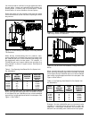
Air delivery above 1800 CFM requires that both sides of
furnace be used for return air, or a combination of one side
and bottom or bottom only.
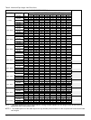
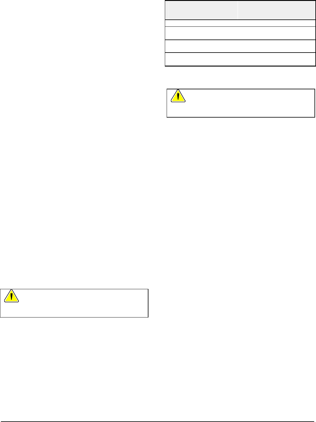
If bottom return air is not used, you must attach a solid
bottom-closure panel to bottom return-air opening. Bottom
closure panel is available from manufacturer. See Table 5
for bottom closure part numbers.
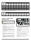
Table 5. Bottom Closure Part Numbers.
GAS
INPUT*
(Btu/hr)
MOTOR*
HORSE-
POWER
BOTTOM CLOSURE
PART NUMBER
54,000 1/3 4045901
72,000
90,000
1/2
4045901
72,000
90,000
3/4 4045902
108,000
126,000
3/4 4045903
* GAS INPUT and MOTOR HP can be found on furnace
rating plate.
WARNING: Failure to install bottom closure panel
could allow combustion products to enter circulating air
stream, resulting in injury or death by asphyxiation.
DUCT DAMPERS
You may balance airflow with dampers installed in each
branch run duct and adjust for even temperature throughout
the heated space. For proper furnace operation, make sure
of the following:
?? Supply air registers and return air grilles are open;
?? Rugs, carpets, drapes or furniture are clear of registers
and grilles;
?? Size and shape of supply air plenum is correct;
?? Number of supply air ducts is correct.
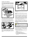
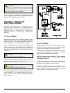
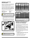
LOCATION OF COOLING COIL
If furnace will share common duct system with a separate
cooling unit, install furnace parallel to or upstream of
cooling unit. This avoids condensation in heating element.
Do not install cooling coil in return-air ductwork. With
parallel flow, dampers must be installed to prevent chilled
air from entering furnace. If dampers are not in full heat or
full cool position, furnace or cooling unit must not operate.
SECTION 10. SELECTING AND
INSTALLING FILTER CABINETS
Properly installed air filters keep blower motor, blower
wheel and cooling coil (if installed) clean. Filters and filter
cabinets are not supplied with this furnace. Filters and filter
cabinets must be field supplied or obtained from the
manufacturer. The manufacturer has bottom and side filter
cabinets available. This furnace was designed for an
external filter(s). Do not install air filters inside furnace
casing. Obtain and install proper filter frames and correctly
sized filters. To inspect, clean or replace air filters, follow
the instructions in the User’s Information Manual.
CAUTION: You must install air filters to keep blower motor,
blower wheel and cooling coil (if installed) clean. Dirty
equipment may reduce system efficiency or cause erratic
control performance and can result in damage to blower
motor, heat exchanger or air conditioner (if installed).