


Page 14 Installer’s Information Manual
Calculate the free area required.
Because combustion and ventilation air ducts run
horizontally, allow 2,000 Btu per hour.
Furnace input (Btu/hr) = Free area required
2,000 Btu/hr
per square inch
90,000 = 45 square inches
2,000
Both of the ducts must have a minimum cross sectional
area of 45 square inches.
SECTION 5. CONDENSATE DRAIN
This furnace produces water as a product of combustion.
Much of this water condenses on the stainless steel tubing
of the heat exchanger and in the vent system. This water
(referred to as condensate) must be drained from the
furnace into a household drain. The following notes should
be considered when connecting condensate drain:
?? The furnace’s drain trap must be primed. This is easily
done by pouring a few cups of water into furnace vent
pipe after drain installation is complete.
?? A frozen or blocked drain line will cause furnace
shutdown and no-heat complaints. Protect drain trap
and drain tubing from freezing.
?? When a condensate pump is used, select a pump
designed for furnace condensate.
SECTION 6. INSTALLING GAS
PIPING
PREPARATION
Refer to the current National Fuel Gas Code ANSI
Z223.1/NFPA 54 or CAN/CGA B149 Installation Codes and
local codes for gas piping requirements and sizing. Pipe
size running to furnace depends on:
?? Length of pipe
?? Number of fittings
?? Specific gravity of gas
?? Input requirements (Btu per hour) of all gas-fired
appliances attached to same main supply line.
Plan furnace gas supply piping so it will not interfere with
removal of burner assembly, front door or blower door for
servicing.
Make sure gas piping is large enough for all appliances
connected to it to operate at once without lowering gas
supply pressure. Failure to do so could cause lighting or
burning problems on any of the appliances.
Always use a pipe thread compound that is resistant to
propane (LP) gas solvent action. Sparingly apply thread
compound to all joints on male threads only, starting two
threads from the end.
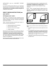
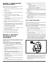
INSTALLATION
Gas supply piping can be installed from either side of
furnace casing. Install gas supply piping according to
Figure 13 and the following instructions.
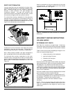
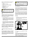
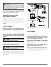
Figure 13. Gas Line Installation.
1. Install a 3-inch long x 1/2” NPT black-iron pipe nipple
through gas entry grommet and into gas-control inlet
elbow. Install a black iron pipe elbow on 3-inch nipple.
Tighten gas tight. Do not over tighten.
2. Install a ground-joint union and a drip leg immediately
upstream of the furnace. Ground-joint union allows
easy servicing of burner assembly and furnace gas
control. Ground-joint union must be listed by a
nationally recognized testing laboratory.
3. Install a manual “equipment” shut-off valve in gas
supply line immediately upstream of ground-joint union.
Equipment shut-off valve must be listed by a nationally
recognized testing laboratory.
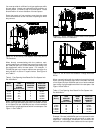
TESTING FOR LEAKS
Isolate furnace and its gas control from gas supply line
during leak checks. Gas-supply line test pressure
determines how you isolate gas control.
The furnace and its gas control must be disconnected from
gas supply piping system at ground joint union during any
pressure testing of the system at test pressures greater
than 1/2 psi (14 inches W.C.).
The furnace must be isolated from gas supply piping
system by turning off equipment shut-off valve during any
pressure testing of the system at test pressures equal to or
less than 1/2 psi (14 inches W.C.).