


Installer’s Information Manual Page 15
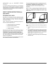
WARNING: When test pressure is above 1/2 psi
(14 inches W.C.), completely disconnect furnace and gas
control from gas supply line. Failure to isolate furnace and
gas control from test pressure could damage them, causing
gas to leak, resulting in fire or explosion.
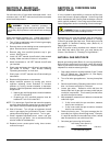
Use a commercial soap solution made to detect leaks and
check all gas piping connections. Bubbles indicate gas
leakage. Seal all leaks before proceeding.
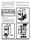
SECTION 7. INSTALLING
ELECTRICAL WIRING
CAUTION: Label all wires prior to disconnection when
servicing controls. Wiring errors can cause improper and
dangerous operation. When replacing original wire, use
same type, color, or equivalent wire. Remember to
renumber wire ends. Verify proper operation after
servicing.
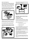
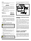
115 VOLT WIRING
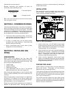
Wire furnace according to the Field Wiring Diagram shown
in Figure 14, local codes, and current National Electrical
Code ANSI/NFPA 70 or Canadian Electrical Code CSA
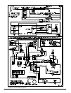
C22.1. Also, see Furnace Wiring Diagram in Figure 15.
Install proper electrical grounding by attaching grounding
source to green wire in furnace junction box. Follow local
codes or in the absence of local codes, the current National
Electrical Code ANSI/NFPA 70 or Canadian Electrical Code
CSA C22.1.
WARNING: Failure to provide a proper electrical
ground could result in electric shock or fire.
Provide furnace with its own separate electrical circuit and
means of circuit protection. Furnace must have an
electrical disconnect switch located at furnace.
WARNING: Failure to provide the above shut-off
means could result in electrical shock or fire.
Use electrical wiring that meets current National Electrical
Code ANSI/NFPA 70 or Canadian Electrical Code CSA
C22.1 and local codes. Use Type T (63 degrees C rise)
wire or equivalent.
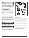
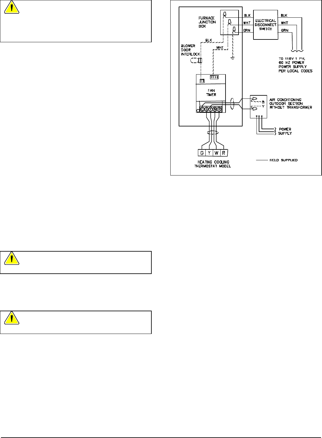
Figure 14. Field Wiring Diagram.
24 VOLT WIRING
Select a location for room thermostat on a draft-free interior
wall that is away from supply and return air registers, lights,
television, direct sunlight, or other heat sources.
Install thermostat following field-wiring diagram in Figure 14
and thermostat manufacturer's instructions. Thermostat
wire should be 18 AWG wire for best results.
NOTE: For proper cooling operation, “Y” wire must be
connected to Fan Timer. “Y” wire controls cooling
speed blower operation.
Set the thermostat's heat anticipator following instructions
provided with thermostat. This furnace will have heat
anticipator current of approximately 0.4 amps.
CAUTION: 24 VAC accessories that draw power from the
furnace's transformer should not be installed on this
furnace. Addition of such accessories may cause improper
furnace operation and limit transformer life.