


Installer’s Information Manual Page 23
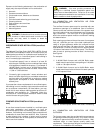
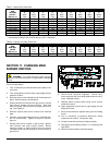
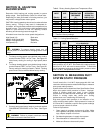
Table 7. Natural Gas Orifice Size.
ELEVATION
GAS Up 2001 3001 4001 5001 6001* 7001* 8001* 9001*
HEATING to to to to to to to to to
VALUE** 2000 3000 4000 5000 6000 7000 8000 9000 10000
(Btu/cu. ft.) Feet Feet Feet Feet Feet Feet Feet Feet Feet
800-849 2.25 2.20 2.15 2.15 2.10 2.05 2.05 2.00 1.95
850-899 2.20 2.15 2.10 2.10 2.05 2.00 2.00 1.95 1.90
900-949 2.15 2.10 2.05 2.05 2.00 1.95 1.95 1.90 1.85
950-999 2.10 2.05 2.00 2.00 1.95 1.90 1.90 1.85 1.80
1000-1049 2.05 2.00 1.95 1.95 1.90 1.85 1.85 1.80 1.75
1050-1099 2.00 1.95 1.90 1.90 1.85 1.80 1.80 1.75 1.75
1100-1149 1.95 1.90 1.85 1.85 1.80 1.80 1.75 1.75 --
1150-1199 1.90 1.85 1.85 1.80 1.75 1.75 -- -- --
* Above 6000 feet, a high-altitude gas conversion kit must be used.
** At standard conditions: 30.0 inches Mercury, 60°F, Saturated.
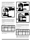
Table 8. Propane (LP) Gas Orifice Size.
ELEVATION
GAS Up 2001 3001 4001 5001 6001* 7001* 8001* 9001*
HEATING* to to to to to to to to to
VALUE 2000 3000 4000 5000 6000 7000 8000 9000 10000
(Btu/cu. ft.) Feet Feet Feet Feet Feet Feet Feet Feet Feet
2500-2550 1.20 1.15 1.15 1.15 1.15 1.10 1.10 1.10 1.05
* Above 6000 feet, a high-altitude gas conversion kit must be used.
SECTION 17. CHANGING MAIN
BURNER ORIFICES
WARNING: To prevent electrical shock and gas
leaks, turn off electrical power and gas before changing
orifices.
Follow this procedure:
1. Turn off electricity at electrical disconnect switch next
to furnace.
2. Turn off equipment shut-off valve in gas supply line just
ahead of furnace.
3. Remove three screws holding burner access panel in
place. Remove burner access panel.
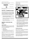
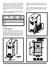
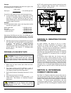
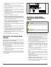
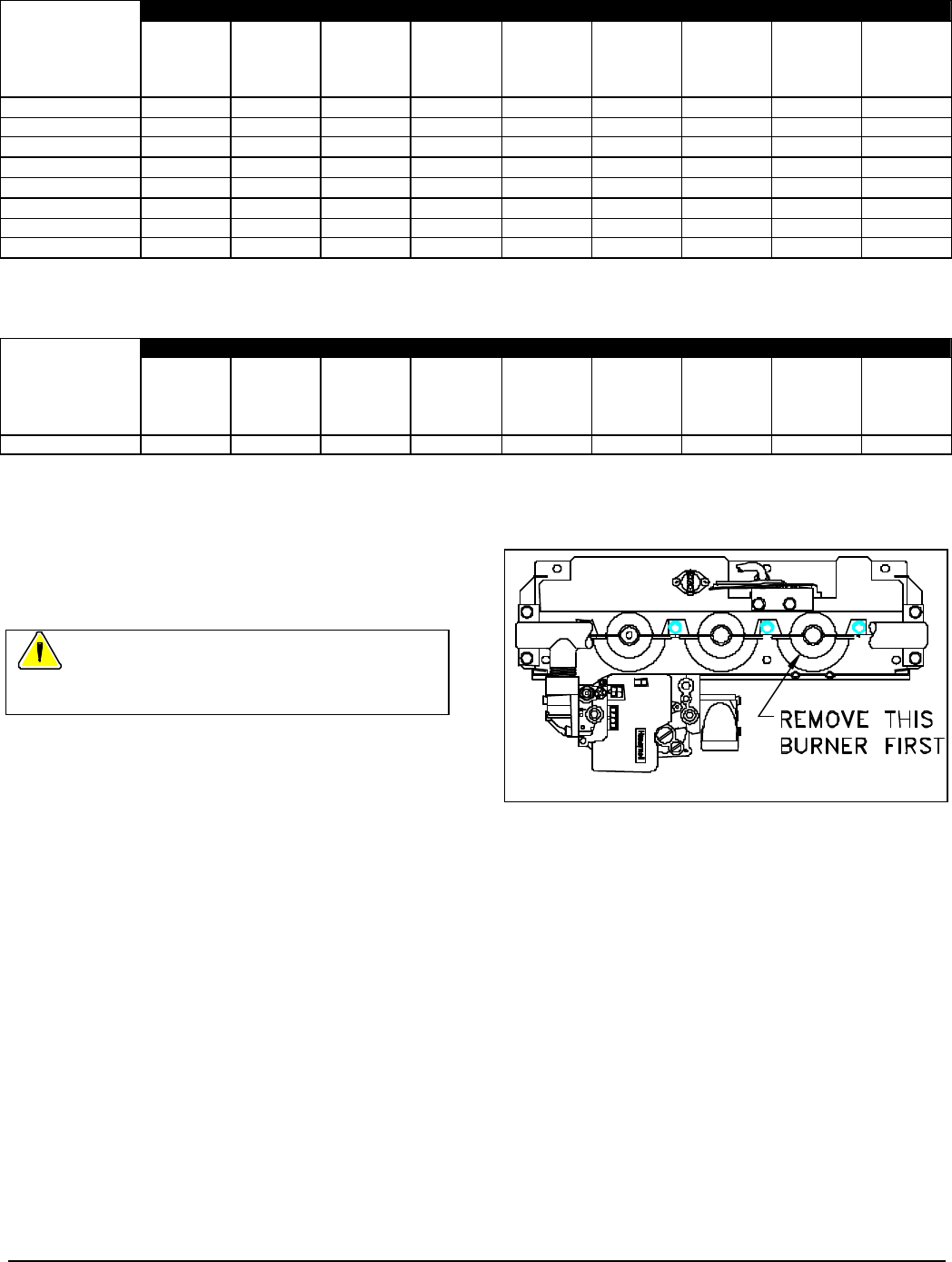
4. Starting with burner farthest from gas control, remove
main burner screws and main burners. Note how
burners overlap. Burner farthest from gas control is on
top. See Figure 21.
5. Remove original main burner orifices from manifold
pipe.
6. Carefully, hand thread new orifices into manifold pipe.
Do not cross-thread. Tighten to torque of 50 inch-
pounds.
7. Starting with burner closest to gas control, replace
main burners and main burner screws. Burner
mounting flange of burner farther from gas control
overlaps burner-mounting flange of burner closest to
gas control.
Figure 21. Main Burner Removal.
8. Check burner carry-over alignment. Burner carry-
overs may touch but not overlap adjacent burner carry-
overs. Replace screws.
9. Replace burner access panel using three screws
removed in step 3.
10. Open equipment shut-off valve in gas supply line just
ahead of furnace.
11. Set room thermostat to highest setting and to heating
mode.
12. Turn on electricity at electrical disconnect switch
located next to furnace. Furnace will light.
13. Visually check that each burner lights promptly.
14. Check gas input following Section 14, "Checking Gas
Input Rate."
15. Reset room thermostat to desired setting.