


Installer’s Information Manual Page 25
5. Make sure that blower speed taps are set for proper
heating and cooling. Refer to Section 18, "Adjusting
Blower Speed." Heating speed should be set
according to Table 9. Cooling speed should be set to
meet cooling equipment requirements. See Table 10
for cooling airflow capacities at 0.5 inch W.C.
6. Place slope gauge near furnace, level and adjust scale
to read 0.00 inches W.C.
7. Insert one static pressure tap into supply-air duct
between furnace and cooling coil or in supply air
plenum for heating only systems. Connect this
pressure tap to positive pressure side of slope gauge.
8. Insert other static pressure tap in return air plenum.
Connect this pressure tap to negative pressure side of
slope gauge.
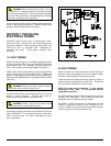
9. Start blower.
?? Blower heating speed can be run by jumping
terminals "R" and "G" on 24-volt terminal block
located on Fan Timer.
?? Blower cooling speed can be run by jumping
terminals "R" and "Y" on 24-volt terminal block
located on Fan Timer.
NOTE: On cooling speed, there is a short on-delay before
blower starts and a 60-second off-delay before blower
stops.
10. Read duct system static pressure from slope gauge.
NOTE: If air filter location is upstream of return-air pressure
tap, static pressure must be adjusted to exclude filter
pressure drop. Do this by subtracting 0.08 inches W.C.
from the measured static pressure.
Duct System = Measured - 0.08 inches W.C.
Static Pressure Pressure
11. Remove jumper wire from 24-volt terminal strip.
Remove pressure taps and seal holes in ductwork.
SECTION 20. MEASURING AIR
TEMPERATURE RISE
You will need 2 thermometers with 1-degree resolution
capable of reading up to 175 degrees F.
Air temperature rise (supply air temperature minus return
air temperature) must be within allowable air-temperature
rise range specified on furnace rating plate and in Table 9.
Follow this procedure:
1. Open supply air registers and return air grilles. Make
sure registers and grilles are free of obstruction from
rugs, carpets, drapes or furniture.
2. Set balancing dampers in supply duct system.
3. Check ductwork for obstructions or leaks.
4. Make sure filters are clean and in place.
5. Make sure that blower speed taps are set for proper
heating and cooling. Refer to Section 18, "Adjusting
Blower Speed." Heating speed should be set
according to Table 9. Cooling speed should be set to
meet cooling equipment requirements. See Table 10
for cooling airflow capacities at 0.5 inch W.C.
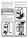
6. Place one thermometer in supply air plenum
approximately 2 feet from furnace. Locate
thermometer tip in center of plenum to ensure proper
temperature measurement.
7. Place second thermometer in return-air duct
approximately 2 feet from furnace. Locate
thermometer tip in center of duct to ensure proper
temperature measurement.
8. Set room thermostat on highest temperature setting.
Operate furnace 6 minutes. Record supply air and
return air temperatures.
9. Calculate air temperature rise by subtracting return air
temperature from supply air temperature.
?? If air temperature rise is above temperature rise
range specified in Table 9, furnace is overfired or
has insufficient airflow. Check gas input following
the instructions in Section 14, "Checking Gas
Input Rate." If air temperature rise is still above
temperature rise range specified, more heating
airflow is needed. Change blower heating speed
to a higher setting following instructions in
Section 18, "Adjusting Blower Speed."
?? If air temperature rise is below temperature rise
range specified in Table 9, furnace is underfired
or has too much airflow. Check gas input
following the instructions in Section 14, "Checking
Gas Input Rate." If air temperature rise is still
below temperature rise range specified, less
heating airflow is needed. Change blower
heating speed to a lower setting following
instructions in Section 18, "Adjusting Blower
Speed."
?? After making adjustments, you must check air
temperature rise to verify that resulting air
temperature rise is within allowable range. If air
temperature rise is still outside temperature rise
range specified in Table 9, check duct system
design with a qualified heating engineer. It may
be necessary to re-size duct work. Recheck air
temperature rise after revising duct systems.
10. Set room thermostat to desired setting.
11. Remove thermometers and seal ductwork holes.
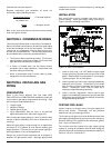
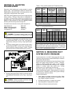
SECTION 21. CHECKING
CONTROLS
Before leaving work site, check to see that all controls are
functioning properly.
You will need a 0 to 15 inch water manometer with 0.1 inch
resolution and a 1/8" NPT manual shut-off valve.
Follow this procedure:
1. Turn off electricity at electrical disconnect switch next
to furnace.
2. Remove three screws holding burner access panel in
place. Remove burner access panel.
3. Turn gas control switch to OFF position.