Note
Scalar Analysis Measurement with User Flatness Corrections,
Example 4
The following example demonstrates how to setup a scalar analysis
measurement (using an HP 8757 Scalar Network Analyzer) of a 2 to
20 GHz test device such as, an amplifier. User flatness correction
is used to compensate for power variations at the test port of a
directional bridge. Follow the instructions to set up the synthesizer,
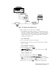
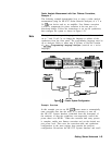
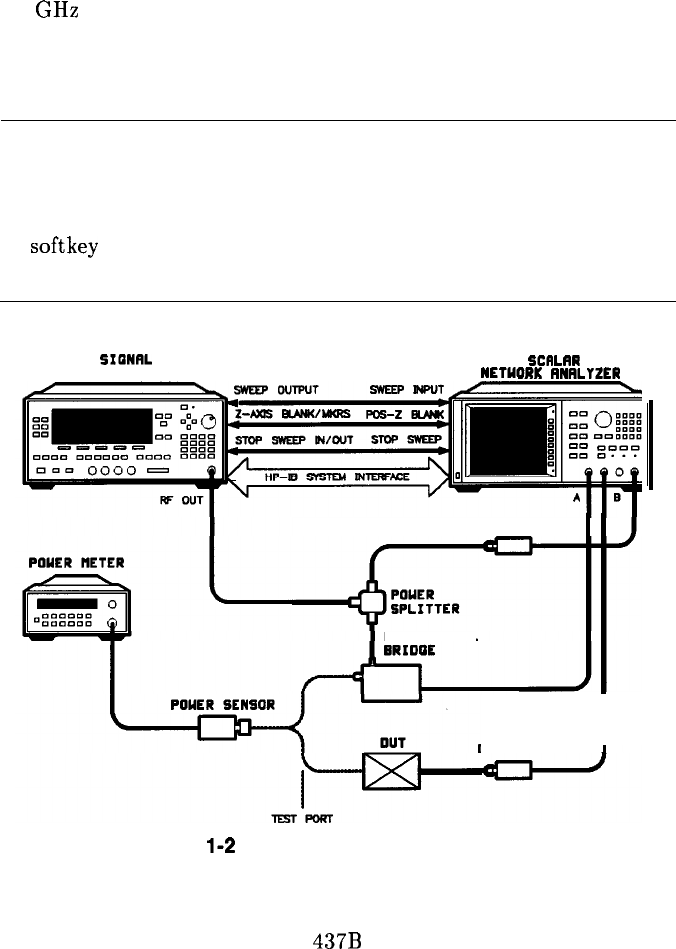
then configure the system as shown in Figure 1-21.
The synthesizer’s rear panel language and address switches must be
set to 7 and 31 (all l’s), to change the language or address of the
synthesizer from the front panel. The programming language must be
set to Analyzer. Refer to menu map 8, System, to find the location
of softkey Programming Language Analyzer (asterisk on = active
language).
SIONRL
ILRR
SYNTHESIZER
I”_
RNRLYZEN
SCF
NETIN-’
DETECTORDETECTOR
OIRECTIONRL
DETECTOR
I
Figure
l-2
1. Scalar System Configuration
Example Overview
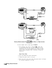
In this example you use an HP
437B
power meter to automatically
enter correction data into the array. It is necessary to turn off
the HP 8757 System Interface (controlled from the front-panel of
the analyzer) so that the synthesizer can temporarily control the
power meter over HP-IB . When the correction data entry process
is complete, enable user flatness correction and set the desired test
port power level. Then store the correction table and synthesizer
configuration in the same register that contains the analyzer
configuration. Re-activate the HP 8757 System Interface and recall
Getting Started Advanced 1-43


