


9
Liquid Lines
Liquid lines should be sized for a minimum pressure drop to prevent
“ashing”. Flashing in the liquid lines would create additional pressure drop
and poor expansion valve operation. If a system requires long liquid lines
from the receiver to the evaporator or if the liquid has to rise vertically
upward any distance, the losses should be calculated to determine whether
or not a heat exchanger is required. The use of a suction to liquid heat
exchanger may be used to subcool the liquid to prevent ashing. This
method of subcooling will normally provide no more than 20
˚
F subcooling
on high pressure systems. The amount of subcooling will depend on the
design and size of the heat exchanger and on the operating suction and
discharge pressures. An additional benet from the use of the suction to
liquid type heat exchanger is that it can help raise the superheat in the
suction line to prevent liquid return to the compressor via the suction line.
Generally, heat exchangers are not recommended on R-22 low temperature
systems. However, they have proved necessary on short, well insulated
suction line runs to provide superheat at the compressor.
Hot Gas Defrost Systems
Hot Gas Defrost systems can be described as reverse cycle, re-evap., or
alternating evaporator. Please see manual H-IM-HGD for Mohave™ systems.
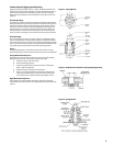
Refrigerant Piping
Install all refrigerant components in accordance with applicable local and
national codes and in accordance with good practice for proper system
operation. The thermostatic expansion valve must be the externally
equalized type. It can be mounted inside the unit end compartment. Mount
the expansion valve bulb on a horizontal run of suction line as close as
possible to the suction header. Use the clamps provided with the valve to
fasten the bulb securely so there is a tight line-to-line contact between the
bulb and the suction line. Suction and hot gas connections are made on the
outside of the unit.
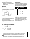
Suction lines should be sloped towards the compressor at the rate of one
(1) inch per ten (10) feet for good oil return. Vertical risers of more than four
(4) feet should be trapped at the bottom with a P-trap. If a P-trap is used, the
expansion valve bulb should be installed between the unit and the trap.
Reverse Cycle System
The hot gas unit coolers can be used in reverse cycle hot gas defrost systems
using multiple evaporators connected to one condensing unit. Generally, not
more than one-third of the system defrosts at one time. During the reverse
cycle defrost, the reversing valve, located in the compressor discharge line,
diverts hot gas through the suction line to the evaporator.
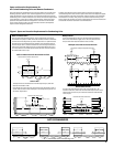
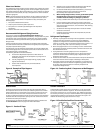
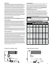
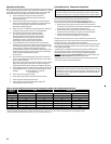
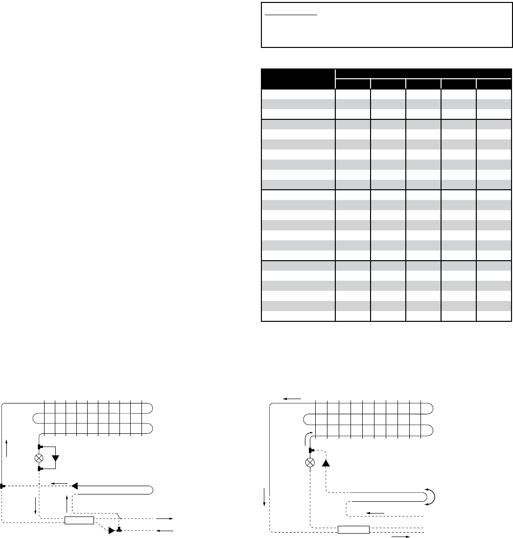
See the piping view in the Reverse Cycle Defrost Piping diagram. The suction
line check valve directs the hot gas through the drain pan loop which
prevents condensate in the pan from freezing. The hot gas exits the loop at
the pan loop outlet header and enters the evaporator through the check
valve assembly. As the hot gas defrosts the coil, heat is removed from the
hot gas and eventually it condenses into a liquid and exits the coil at the
distributor side port. The liquid then ows through the check valve of the
thermostatic expansion valve bypass assembly, around the thermostatic
expansion valve, and into the system liquid line. The liquid refrigerant then
feeds other evaporators on the cooling cycle, evaporates, and returns to the
compressor through their suction lines.
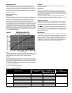
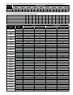
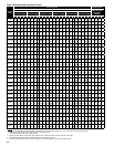
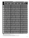
Hot gas line sizes for R-22, R404A and R507
System Capacity
BTU/Hr
Equivalent Discharge Length (Ft.)
25 50 75 100 150
4,000 1/2 1/2 1/2 1/2 1/2
5,000 1/2 1/2 1/2 1/2 1/2
6,000 1/2 1/2 1/2 5/8 5/8
7,000 1/2 1/2 5/8 5/8 5/8
8,000 1/2 5/8 5/8 5/8 5/8
9,000 1/2 5/8 5/8 5/8 5/8
10,000 1/2 5/8 5/8 5/8 5/8
12,000 5/8 5/8 5/8 7/8 7/8
14,000 5/8 5/8 7/8 7/8 7/8
16,000 5/8 5/8 7/8 7/8 7/8
18,000 5/8 7/8 7/8 7/8 7/8
20,000 5/8 7/8 7/8 7/8 7/8
25,000 7/8 7/8 7/8 7/8 1-1/8
30,000 7/8 7/8 7/8 1-1/8 1-1/8
35,000 7/8 7/8 1-1/8 1-1/8 1-1/8
40,000 7/8 1-1/8 1-1/8 1-1/8 1-1/8
45,000 7/8 1-1/8 1-1/8 1-1/8 1-1/8
50,000 7/8 1-1/8 1-1/8 1-1/8 1-1/8
60,000 1-1/8 1-1/8 1-1/8 1-3/8 1-3/8
70,000 1-1/8 1-1/8 1-3/8 1-3/8 1-3/8
80,000 1-1/8 1-1/8 1-3/8 1-3/8 1-5/8
90,000 1-1/8 1-3/8 1-3/8 1-5/8 1-5/8
100,000 1-1/8 1-3/8 1-3/8 1-5/8 1-5/8
Note: Use next larger hot gas line size for -20
0
F. and lower suction temperatures.
EVAP. COIL
TXV
PAN LOOP
THREE-PIPE DEFROST PIPING
CHECK
VALVE
HOT GAS LINE
LIQUID LINE
SUCTION LINE
HEAT – X
EVAP. COIL
TXV
PAN LOOP
CHECK VALVE
REVERSE CYCLE DEFROST PIPING
CHECK VALVE
CHECK
VALVE
LIQUID
LINE
SUCTION
LINE
HEAT – X
IMPORTANT:
It is imperative that with the alternating evaporator hot
gas defrost system, no more that 25% of the operating
refrigeration load be in defrost at any time.
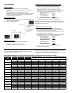
Three Pipe System
The three pipe system (sometimes called re-evap.) uses three pipes: one for
liquid line, one for suction line, and one for hot gas line. In addition, a re-
evaporator accumulator is used at the suction outlet of the evaporator. The
hot gas is taken from the discharge line between the compressor and the
condenser, through a hot gas solenoid valve, then to the evaporator drain
pan circuit, distributor tee, through the coil. See the Three-Pipe Defrost
Piping Diagram for typical piping at the evaporator coil.
Alternating Evaporator System
In the alternating evaporator hot gas defrost system, a third line is taken
o the compressor discharge line as the re-evap system. It is piped with
solenoids at each evaporator, so that hot gas defrost is accomplished on one
or more evaporators while the remaining evaporators continue to function
in a normal manner. The liquid from defrosting evaporators is reintroduced
to the main liquid line and it is necessary that 75% or greater capacity be
retained in the normal refrigeration cycle to oset the capacity that is being
removed by the units on the hot gas defrost.