


16
System Balancing - Compressor Superheat
IMPORTANT:
In order to obtain the maximum capacity from a system, and to ensure
trouble-free operation, it is necessary to balance each and every system.
This is extremely important with any refrigeration system.
The critical value which must be checked is suction superheat.
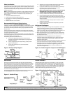
Suction superheat should be checked at the compressor as follows:
Measure the suction pressure at the suction service valve of the
compressor and determine the saturation temperature corresponding
to this pressure from a “Temperature-Pressure” chart.
Measure the suction temperature of the suction line about one
foot back from the compressor using an accurate thermometer.
Subtract the saturated temperature from the actual
suction line temperature. The dierence is superheat.
Too low a suction superheat can result in liquid being returned to the
compressor. This will cause dilution of the oil and eventual failure of the
bearings and rings or in the extreme case, valve failure.
Too high a suction superheat will result in excessive discharge temperatures
which cause a break down of the oil and results in piston ring wear, piston
and cylinder wall damage.
It should also be remembered that the system capacity decreases as the
suction superheat increases. For maximum system capacity, suction
superheat should be kept as low as is practical. Copeland mandates a
minimum superheat of 20˚F at the compressor. We recommend that the
superheat at the compressor be between 20˚F and 30˚F.
If adjustments to the suction superheat need to be made, the expansion
valve at the evaporator should be adjusted.
1.
2.
3.
Operational Check Out
After the system has been charged and has operated for at least two hours at
normal operating conditions without any indication of malfunction, it should
be allowed to operate overnight on automatic controls. Then a thorough
recheck of the entire system operation should be made as follows:
Check compressor discharge and suction pressures.
If not within system design limits, determine why and
take corrective action.
Check liquid line sight glass and expansion valve operation. If
there are indications that more refrigerant is required, leak test
all connections and system components and repair any
leaks before adding refrigerant.
Observe oil level in compressor crankcase sight glass. Add oil as
necessary to bring level to bottom 1/4 of the sight glass.
Thermostatic expansion valves must be checked
for proper superheat settings. Feeler bulbs must be
in positive contact with the suction line and should
be insulated. Valves set at high superheat will lower
refrigeration capacity. Low superheat promotes
liquid slugging and compressor bearing washout.
Using suitable instruments, carefully check line voltage and
amperage at the compressor terminals. Voltage must be within
10% of that indicated on the condensing unit nameplate. If high
or low voltage is indicated, notify the power company.
If amperage draw is excessive, immediately determine the cause
and take corrective action. On three phase motor compressors,
check to see that a balanced load is drawn
by each phase.
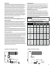
The maximum approved settings for high pressure controls on
our air cooled condensing equipment is 425 psig. On air cooled
systems, check as follows:
Disconnect the fan motors or block the condenser inlet air. Watch
high pressure gauge for cutout point. Recheck all safety and
operating controls for proper operation and adjust if necessary.
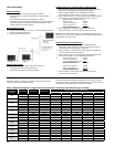
Check defrost controls for initiation and termination settings, and
length of defrost period. Set fail safe at length of defrost + 25%.
Example: 20 minute defrost + 5 minutes
= 25 minute fail safe
Check drain pan for proper drainage.
Check winter head pressure controls for pressure setting.
Check crankcase heater operation if used.
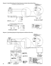
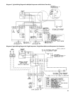
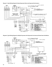
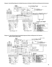
Install instruction card and control system diagram for
use of building manager or owner.
a)
b)
c)
d)
e)
f)
g)
h)
i)
j)
k)
NOTE:
All adjustable controls and valves must be eld adjusted to meet desired
operation. There are no factory preset controls or valve adjustments. This
includes low pressure, high pressure, adjustable head pressure systems
and expansion valves.
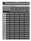
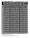
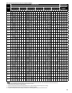
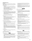
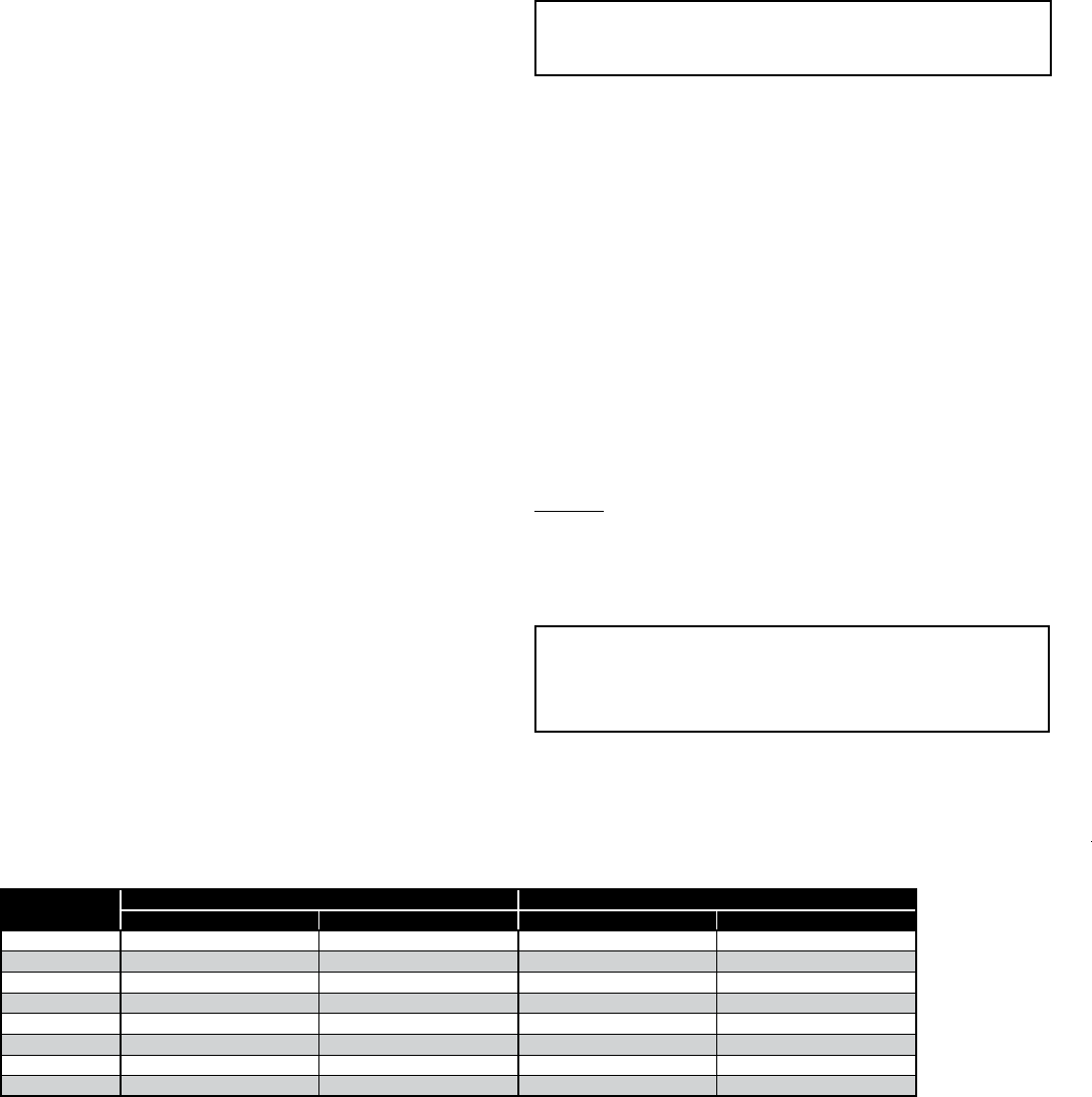
Table 9. Recommended Low Pressure Control Settings for Outdoor Air Cooled Condensing Units
*Minimum
Temp. ˚F
R-22 R-404A/R-507
Cut-In PSI Cut-Out PSI Cut-In PSI Cut-Out PSI
50 70 20 90 35
40 55 20 70 35
30 40 20 55 35
10 30 10 45 25
0 15 0 25 7
-10 15 0 20 1
-20 10 0 12 1
-30 6 0 8 1"Hg.
* Minimum ambient or box temperature anticipated, high pressure control setting: R-22, 360 PSI; R-404A, R-507, 400 PSI
* The standard preset low pressure switch used for pumpdown is set for 15 PSI cut in / 4 PSI cut out and is a good setting for most pumpdown systems
* ZB Scroll compressors should be set for 25 PSI cut in / 17 PSI cut out (R-404A / R-507)