


17
Electric Defrost Troubleshooting
The electric defrost units are relatively simple and trouble-free in operation:
Timer
If the system does not go through its proper sequence , check timer
operation through a defrost cycle. Check for loose wires or terminals. Before
replacing timer, check other components.
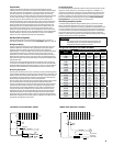
Operation of Paragon Timer
To set time of day grasp knob which is in the center of the inner (fail-safe) dial
and rotate it in a counter-clockwise direction. This will cause the outer (24
hour) dial to revolve. Line up the correct time of day on the outer dial with
the time pointer. Do not try to set the time control by grasping the other (24
hour) dial. Place pins in the outer dial at the time of day that defrost
is required.
Operation of Grasslin Timer
To set the time, turn the minute hand clockwise until the time of day (and
AM or PM) on the outer dial is aligned with the triangle marker on the inner
dial. Do not rotate minute hand counter-clockwise. Move the white tab
(tripper) on the outer dial outward at each desired initiation time. Each white
tab (tripper) is a 15 minute interval and provides 15 minutes of defrost. For
longer defrost duration, move additional tabs (following in time) from the
initiation tab. For example, if a 45 minute defrost is to start at 7:00 AM, move
the tabs outward that lie between 7:00 - 7:15, 7:15 - 7:30 and 7:30 - 7:45 on
the AM side of the dial. The defrost will initiate at 7:00 AM and time terminate
at 7:45 AM (if temperature termination does not occur rst). For models with
plastic cover on timer assembly; re-install cover after adjustment.
NOTE:
After correcting faulty condition it is essential that the coil and unit be
free of ice before placing unit back on automatic operation.
NOTES:
1. Lockout relays or normally closed switch of auxiliary contact on the
compressor contactor may be wired to defrost contactor. Its purpose
is to prevent energizing of the defrost heaters until the compressor has
pumped down and stopped, thus keeping power demand to a minimum.
2. If the control voltage is to remain energized for any period of time with
the compressor disabled, remove the defrost clock pins to prevent the
defrost heaters from energizing.
3. A Preventative Maintenance schedule should be set up as soon as
possible after start-up to maintain equipment integrity.
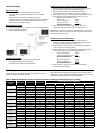
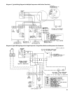
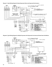
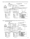
General Sequence of Operation
Refrigeration Cycle
Power is supplied to the timer at terminals “1” and “N”.
The fan delay and the defrost termination thermostat is closed in the fan
delay position and open in the defrost termination position.
The unit cooler fans run continuously.
The defrost heaters are o.
The room thermostat closes when the temperature rises above the
desired setting.
The liquid line solenoid is energized and opens, which allows
liquid refrigerant to ow through the unit cooler.
The low pressure control closes when the suction pressure rises
above the cutin setting of the control.
On systems with oil pumps, the oil safety control is closed. If the
net oil pressure is less than 9 PSIG for more than 120
seconds, the oil safety opens, thus breaking the circuit
to the compressor contactor holding coil. The compressor will
not operate. This control is reset manually and must be
reset before the compressor can be restarted.
The compressor contactor closes. The compressor and condenser
fan start simultaneously.
The room temperature gradually decreases to the desired temperature.
Once the desired temperature is reached, the thermostat opens and the
liquid line solenoid closes, stopping refrigerant ow through
the evaporator.
Suction pressure decreases and the compressor contactor opens
when the pressure drops below the cutout setting on the low
pressure control. The compressor and condenser fan stop running.
This cycle is repeated as many times as necessary to satisfy the
room thermostat.
Frost starts to form on the evaporator coil and continues to form
until the defrost cycle is initiated.
Defrost Cycle
The defrost cycle starts automatically by the timer at predetermined
times. Typical settings are two to four defrost cycles per day for freezers.
For heavier frost loads additional settings may be required.
Switch “2” to “4” opens in the timer which breaks the circuit to the room
thermostat, liquid line solenoid, and evaporator fan motors, allowing
the compressor to pump down and shut o. Simultaneously
switch “1” to “3” closes in the timer allowing current to ow to one side
of the defrost heater contactor. When the compressor
shuts o, an auxiliary contact will send power to the contactor holding
coil; thus, energizing the defrost heaters.
The heaters raise the temperature of the coil to 32˚F causing the frost to
melt o the coil.
When the coil warms to 45˚F to 55˚F, the defrost termination thermostat
closes, which allows current to the switching solenoid in the timer
allowing the refrigeration cycle to begin again.
The evaporator heaters are o. If the termination thermostat fails to
close, the fail-safe set on the timer will terminate defrost.
The low pressure control closes and the compressor will start.
When the coil temperature reaches 23˚F to 30˚F, the fan
delay closes. This allows the current to ow to the fan
motors. The fan motors start running.
The system will now operate in the refrigeration cycle until another
defrost period is initiated by the timer.
1.
2.
3.
4.
5.
6.
7.
8.
9.
10.
11.
12.
13.
1.
2.
3.
4.
5.
6.
7.
8.