


14
Evacuation and Leak Detection
Due to the smaller molecule size of HFC’s, they will tend to leak more readily
than CFC’s. Consequently, it is of the utmost importance that proper system
evacuation and leak detection procedures be employed.
Copeland recommends a minimum evacuation to 500 microns. In addition,
a vacuum decay test is strongly recommended to assure there is not a
large pressure dierential between the system and vacuum pump. Good
evacuation processes include frequent vacuum pump oil changes and large
diameter, short hose connections to both high and low sides of the system
preferably using bronze braided hose.
Leak detection can be carried out in the conventional manner.
If HCFC or CFC tracer gas is used, care must be taken to completely remove
all traces of the gas prior to introducing HFC’s.
Electronic leak detectors are now available that will sense HFC’s. This is
considered preferable since it removes the possibility of chlorine remaining
in the system after leak testing with HCFC’s and/or CFC’s. There is a view that
even small quantities of chlorine may act as a catalyst encouraging copper
plating and/or corrosion and should therefore be avoided.
WARNING:
HFC-134a has been shown to be combustible at pressure as low as 5.5
psig (at 350˚F) when mixed with air at concentrations more than 60%
air by volume.
At lower temperature, higher pressures are required to support
combustion. Therefore, air should never be mixed with HFC-134a for
leak detection.
Within the last several years, manufacturers have developed uorescent dye
leak detection systems for use with refrigerants. These dyes mix with the
lubricant and, when exposed to an ultraviolet light “uoresce,” indicates the
location of leaks. Copeland has tested and approved the Rigid “System Safe”
dye and found it to be compatible with the compressor materials in systems.
Leak Testing
After all lines are connected, the entire system must be leak tested. The
complete system should be pressurized to not more than 150 psig with
refrigerant and dry nitrogen (or dry CO
2
). The use of an electronic type leak
detector is highly recommended because of its greater sensitivity to small
leaks. As a further check it is recommended that this pressure be held for a
minimum of 12 hours and then rechecked. For a satisfactory installation, the
system must be leak tight.
Line Insulation
After the nal leak test, refrigerant lines exposed to high ambient conditions
should be insulated to reduce heat pickup and prevent the formation of
ash gas in the liquid lines. Suction lines must always be insulated with 3/4"
wall Armstrong “Armaex” or equal. When required, Liquid lines should be
insulated with 1/2 inch wall insulation or better. The insulation located in
outdoor environments should be protected from UV exposure to prevent
deterioration of insulating value.
Evacuation
CAUTION:
Do not use the refrigeration compressor to evacuate the system. Do
not start the compressor while it is in a vacuum.
A good, deep vacuum pump should be connected to both the low and high
side evacuation valves with copper tube or high vacuum hoses (1/4" ID
minimum). If the compressor has service valves, they should remain closed.
A deep vacuum gauge capable of registering pressure in microns should be
attached to the system for pressure readings.
A shut o valve between the gauge connection and vacuum pump should
be provided to allow the system pressure to be checked after evacuation. Do
not turn o vacuum pump when connected to an evacuated system before
closing shut o valve.
The vacuum pump should be operated until a pressure of 1,500 microns
absolute pressure is reached — at which time the vacuum should be broken
with the refrigerant to be used in the system through a drier until the system
pressure rises above “0” psig.
NOTE:
Refrigerant used during evacuation cannot be vented. Reclaim all used
refrigerant. EPA regulations are constantly being updated. Ensure your
procedure follows correct regulations.
Repeat this operation a second time.
Open the compressor service valves and evacuate the entire system to 500
microns absolute pressure. Raise the pressure to 2 psig with the refrigerant
and remove the vacuum pump.
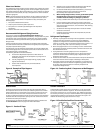
Refrigerant Charging Instructions
Install a liquid line drier in the refrigerant supply line between the
service gauge and the liquid service port of the receiver. This
extra drier will insure that all refrigerant supplied to the
system is clean and dry.
When initially charging a system that is in a vacuum, liquid
refrigerant can be added directly into the receiver tank.
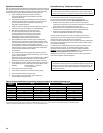
Check equipment catalog for refrigerant capacity. System
refrigerant capacity is 90% of receiver capacity. Do not add more
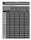
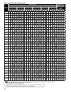
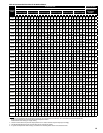
refrigerant than the data tag indicates, unless the line run exceeds
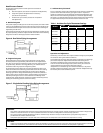
25ft. Then, add additional refrigerant as per the chart on page 30.
Weigh the refrigerant drum before charging so an accurate record
can be kept of the weight of refrigerant put in the system.
Start the system and nish charging until the sight glass indicates
a full charge and the proper amount has been weighed in. If the
refrigerant must be added to the system through the
suction side of the compressor, charge in vapor form only. Liquid
charging must be done in the high side only or with
liquid metering devices to protect the compressor.
Low Head Pressure Systems
If you are charging the system by using a clear sight glass as an indication of
proper charge the following must be considered.
Check the condensing temperature. It must be above 105˚F. If not, it will be
necessary to reduce the amount of air going through the condenser from
fans still running. Simply reduce the eective condenser face area to raise the
discharge pressure above the equivalent 105˚F condensing temperature and
then proceed to charge to clear the sightglass. Adjust evaporator superheat
at this time. Return to full condenser face area and allow the system to
balance.
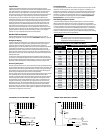
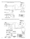
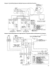
Field Wiring
WARNING:
All wiring must be done in accordance with applicable codes and local
ordinances.
The eld wiring should enter the areas as provided on the unit. The wiring
diagram for each unit is located on the inside of the electrical panel door.
All eld wiring should be done in a professional manner and in accordance
with all governing codes. Before operating unit, double check all wiring
connections, including the factory terminals. Factory connections can vibrate
loose during shipment.
The serial data tag on the unit is marked with the electrical characteristic
for wiring the unit.
Consult the wiring diagram in the unit cooler and in the condensing unit
for proper connections.
Wire type should be of copper conductor only and of the proper
size to handle the connected load.
The unit must be grounded.
For multiple evaporator systems, the defrost termination controls
should be wired in series. Follow the wiring diagrams for multiple
evaporator systems carefully. This will assure complete defrost of
all evaporators in the system.
Multiple evaporator systems should operate o of one thermostat.
If a remote defrost timer is to be used, the timer should be located
outside the refrigerated space.
For air cooled condensers, due to multiple low amp motors, we
recommend using time delay fuse protection instead
of circuit breakers.
1.
2.
3.
4.
1.
2.
3.
4.
5.
6.
7.
8.