


4
Requirements for Remote and Water Cooled
Condensing Units
General Installation
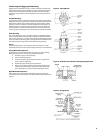
The indoor compressor units are designed to be used with a remote
condenser. The water cooled units are similar, except that they have an
integral water cooled condenser. Inlet and outlet water connections are to
be made in the eld. On units having a compressor water jacket, incoming
water shall be routed through the jacket prior to entering the condenser. For
cleaning purposes, condenser end plates can be removed to give access to
the water tubes. Cleaning is accomplished by a simple spiral tool powered
by an ordinary electric drill. During installation, allow space for cleaning the
condenser. Commercial equipment of this type is intended for installation
by qualied refrigeration mechanics.
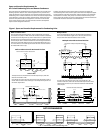
Typical Arrangements
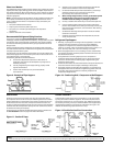
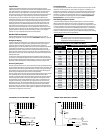
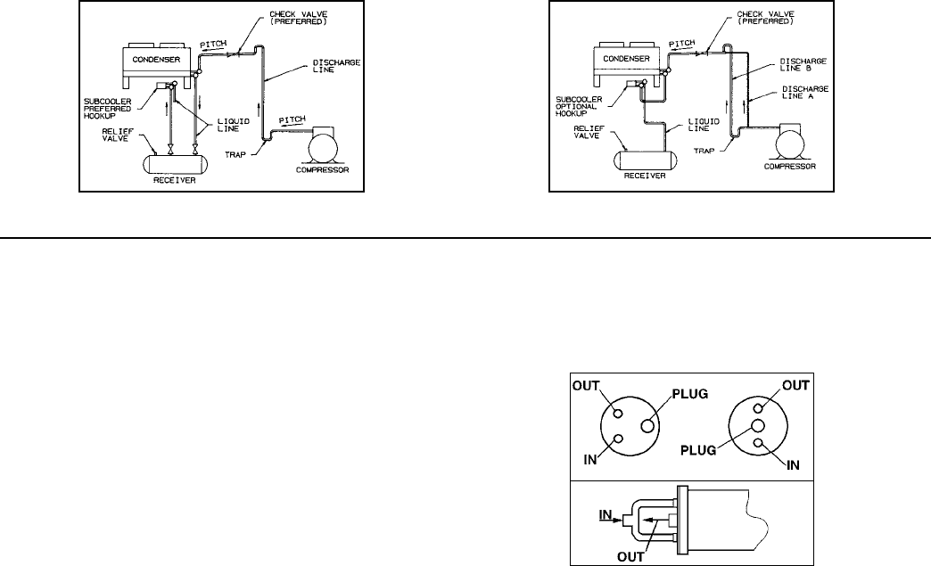
Diagram 1 illustrates a typical piping arrangement involving a remote
condenser located at a higher elevation, as commonly encountered when
the condenser is on a roof and the compressor and receiver are on grade
level or in a basement equipment room.
In this case, the design of the discharge line is very critical. If properly sized
for full load condition, the gas velocity might be too low at reduced loads
to carry oil up through the discharge line and condenser coil. Reducing the
discharge line size would increase the gas velocity suciently at reduced
load conditions; however, when operating at full load, the line would be
greatly undersized, and thereby creating an excessive refrigerant pressure
drop. This condition can be overcome in one of two of the following ways:
The discharge line may be properly sized for the desired pressure
drop at full load conditions and an oil separator installed at the
bottom of the trap in the discharge line from the compressor.
1.
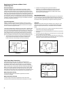
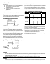
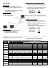
City & Tower Water Connections
In the refrigeration industry “City” and “Tower” are designations of
temperature and ow conditions, not applications. The term “City” refers
to operating conditions where incoming water is 75˚F, and condensing
temperature is 105˚F. “Tower” refers to a higher temperature relationship
which is normally 85˚F, incoming water and 105˚F condensing temperature.
Water circuits in some condenser models provide a center, or Tower, outlet
connection to allow divided inlet water ow. This extra water port reduces
water velocity, water pressure drop, and condenser wear in applications such
as cooling towers where higher inlet temperatures and water ows occur.
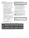
Water Connections for City
For City water (open system) high pressure applications, the Tower
connections is plugged.
Water Connections for Tower
For Tower usage and low pressure applications, both normal water
connections will be used as inlets and the tower connection as an outlet.
Diagram 1 Diagram 2
Figure 2. Water Connections
A double riser discharge line may be used as shown in
Diagram 2. Line “A” should be sized to carry the oil at minimum
load conditions and the line “B” should be sized so that at the
full load conditions both lines would have sucient ow velocity
to carry the oil to the condenser.
Water Regulating Valve
Using this control on the water cooled condensing units, the head pressure
can be maintained by adjusting the ow of water through the condenser
section. This type control is most often located on the water entering side of
the condenser and is regulated by the refrigerant condensing pressure.
Subcooler
Diagrams 1 and 2 below show typical subcooler piping. Diagram 1 is the
preferred connection with receiver as it provides maximum subcooling.
Diagram 2 may be used if the receiver is located far from the condenser.
Notes:
All oil traps are to be as short in radius as possible. Common practice is
to fabricate the trap using three 90 degree ells.
Pressure relief valves are recommended at the condenser for protection
of the coil.
A pressure valve at the high point in the discharge line is recommended
to aid in removing non-condensables.
The placement of a subcooler should be that it does not interfere with
normal airow of the condenser. Increased static of the unit could cause
a decrease in system capacity and fan motor damage.
2.
1.
2.
3.
4.