


10
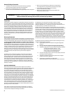
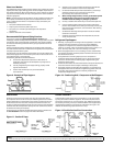
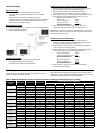
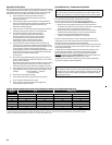
Pipe size example:
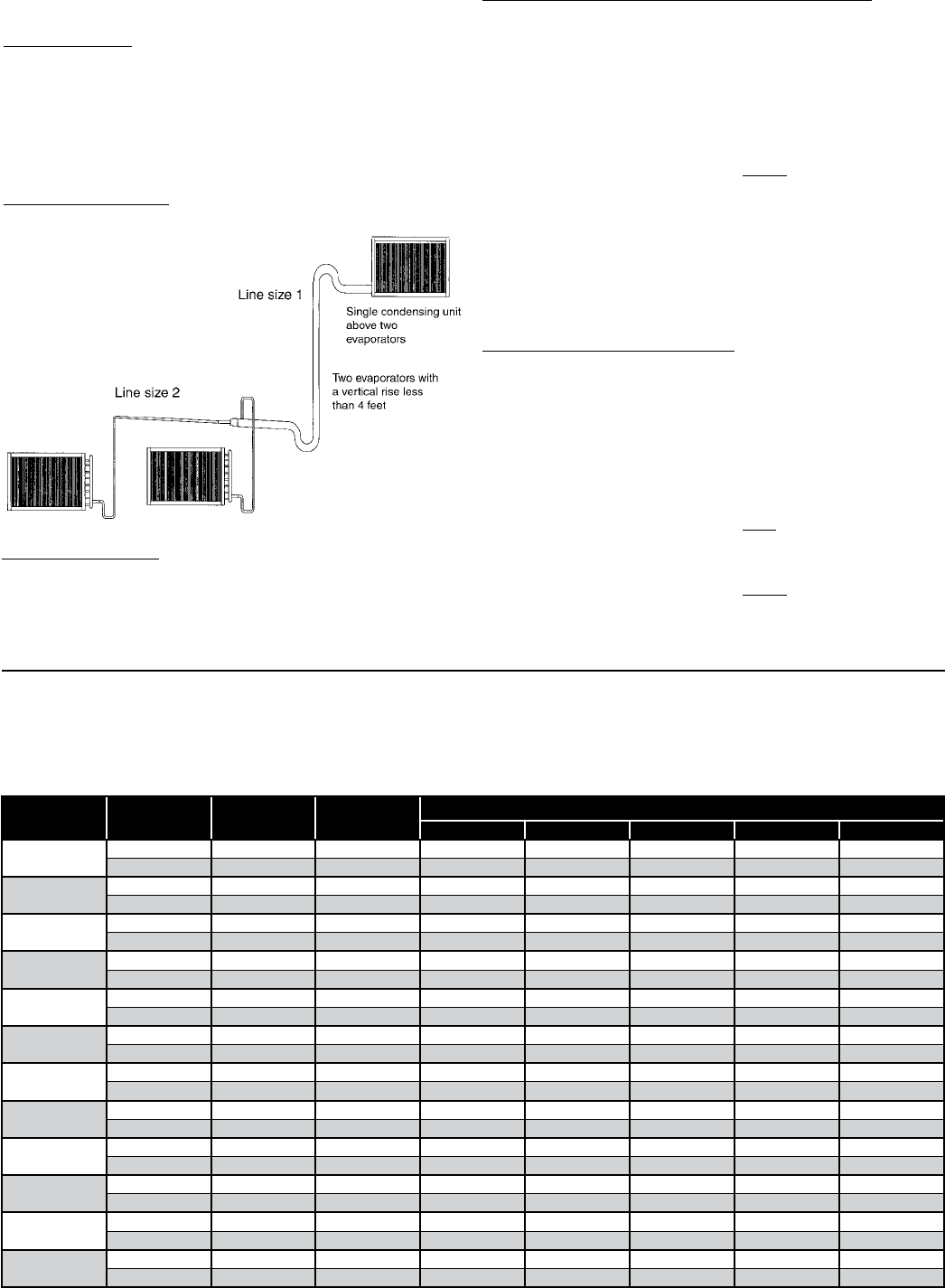
Given: -10°F Freezer with one system having (2) evaporators
• One condensing unit rated at 24,000 BTUH’s @ -20°F SST R404A
refrigerant.
• Two evaporators each rated at 12,000 BTUH’s @ 10°F TD.
• 100 feet of actual line run between condensing unit to rst evaporator
and 20 feet of actual line run between the rst evaporator and the
second evaporator (see gure below).
How to gure line sizes:
Determine equivalent line run = actual run + valves and tting allowances.
Use Line Sizing Tables to size lines.
Note any special considerations.
1.
2.
3.
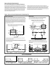
Fittings in this system:
• (6) 90° elbows in main line plus a 90° turn through a tee.
• (5) addtional 90° elbows to rst evaporator.
• (4) additional 90° elbows to second evaporator.
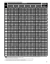
Determine line size 1 (main line from condensing unit):
Main line from the condensing unit to be sized for the total capacity
(balance) of the whole system of 24,000 BTUH’s (Table 8).
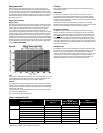
Refer to 24,000 @100 feet at -20°F SST R404A on the chart.
You will nd the suction line to be 1-3/8" and 1/2" liquid line.
Refer to Table 5. For every 1-3/8" 90° elbow you must add 4 equivalent
feet of pipe and 2.5 equivalent feet of pipe for each 1-3/8" tee.
Therefore, total equivalent line run =
Actual line run 100 feet
+ (6) 1-3/8" elbows @ 4' 24 feet
+ (1) 1-3/8" tee @ 2.5' 2.5 feet
Total equivalent line run 126.5 feet
Refer to Table 8. For 126.5 total equivalent feet, the suction
line size should be 1-3/8" and the liquid line stays at 1/2" line.
Note: The gray shaded areas on Table 8. For 24,000 BTUH’s, the maximum
suction riser is 1-1/8" to insure proper oil return and pressure drop from the
bottom p-trap to the top p-trap.
1.
2.
3.
4.
Determine line size 2 (evaporators):
Line sizing to each evaporator is based on 12,000 BTUH’s and
equivalent run from condensing unit. First evaporator has an 105 ft.
run and the second evaporator has a 120 ft. run.
Table 8 indicates 1-1/8" suction for the rst evaporator and indicates
1-1/8" suction for the second evaporator.
Refer to Table 5. Each 1-1/8" 90° elbow adds 3 equivalent feet of pipe.
Each 90° turn through a 1-1/8" tee adds 6 equivalent feet.
Actual line run (evap 1) 105 feet
+ (5) 1-1/8" elbows @ 3' 15 feet
+ (1) 90° turn through tee @ 6' 6 feet
Total equivalent line run 126 feet
Actual line run (evap 2) 120 feet
+ (4) 1-1/8" elbows @ 3' 12 feet
Total equivalent line run 132 feet
Table 8 indicates 1-1/8" suction line and 3/8" liquid line from
main line to both evaporators.
1.
2.
3.
4.
5.
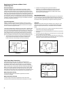
Unit Cooler Piping
Evap. 1
Evap. 2
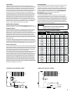
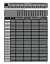
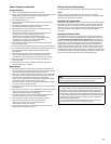
Table 3. Weight of Refrigerants in Copper Lines During Operation (Pounds per 100 lineal feet of type "L" tubing)
Line Size O.D.
(Inches)
Refrigerant Liquid Line Hot Gas Line
Suction Line at Suction Temperature
-40˚F
-20˚F 0˚F +20˚F +40˚F
3/8
22 3.9 0.22 0.02 0.03 0.04 0.06 0.08
R507, 404A 3.4 0.31 0.03 0.04 0.06 0.09 0.13
1/2
22 7.4 0.41 0.03 0.05 0.07 0.11 0.15
R507, 404A 6.4 0.58 0.04 0.07 0.13 0.16 0.24
5/8
22 11.8 0.65 0.05 0.08 0.12 0.17 0.25
R507, 404A 10.3 0.93 0.07 0.11 0.17 0.25 0.35
7/8
22 24.4 1.35 0.10 0.16 0.24 0.36 0.51
R507, 404A 21.2 1.92 0.15 0.23 0.37 0.51 0.72
1-1/8
22 41.6 2.30 0.17 0.28 0.42 0.61 0.87
R507, 404A 36.1 3.27 0.26 0.39 0.63 0.86 1.24
1-3/8
22 63.5 3.50 0.27 0.42 0.64 0.93 1.33
R507, 404A 55.0 4.98 0.40 0.58 0.95 1.32 1.87
1-5/8
22 90.0 4.96 0.37 0.59 0.90 1.33 1.88
R507, 404A 78.0 7.07 0.56 0.82 1.35 1.86 2.64
2-1/8
22 156 8.61 0.65 1.03 1.57 2.30 3.26
R507, 404A 134 12.25 0.98 1.43 2.35 3.23 4.58
2-5/8
22 241 13.70 1.01 1.59 2.42 3.54 5.03
R507, 404A 209 18.92 1.51 2.21 3.62 5.00 7.07
3-1/8
22 344 18.95 1.44 2.28 3.45 5.05 7.18
R507, 404A 298 27.05 2.16 3.15 5.17 7.14 9.95
3-5/8
22 465 25.60 1.94 3.08 4.67 6.83 9.74
R507, 404A 403 36.50 2.92 4.25 6.97 19.65 13.67
4-1/8
22 605 33.40 2.53 4.01 6.08 8.90 12.70
R507, 404A 526 47.57 3.80 5.55 9.09 12.58 17.80
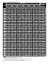
Line Sizing
The following Tables 7 and 8 indicate liquid lines and suction lines for all
condensing units for R22, R404A, and R507.
When determining the refrigerant line length, be sure to add an allowance
for ttings. See Table 5. Total equivalent length of refrigerant lines is the sum
of the actual linear footage and the allowance for ttings.