


6
CAUTION:
Under no circumstance should all condenser motors be allowed to cycle o on one control. At least one motor shall be wired to operate at all times.
Under most circumstances, the condenser motor nearest the inlet header should remain on whenever the compressor is operating.
CAUTION:
Fans closest to the headers should not be cycled on standard temperature or pressure controls. Dramatic temperature and pressure changes at the
headers as a result of fan action can result in possible tube failure. Fan motors are designed for continuous duty operation.
Fan cycling controls should be adjusted to maintain a minimum of (5) minutes on and (5) minutes o. Short cycling of fans may result in a
premature failure of motor and/or fan blade.
Compressors operating below +10°F SST must have air owing over the compressor at all times when the compressor is running.
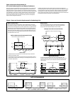
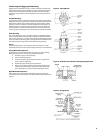
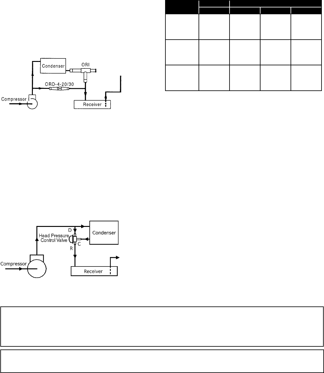
Figure 6. Dual Valve Piping Arrangement
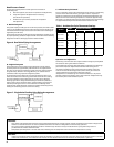
Figure 7. Single Valve Flooding Valve Piping Arrangement
Head Pressure Control
Several types of head pressure control systems are available on
condensing units:
Dual Valve System. (See section on operation and adjustment.)
Single Valve system. No adjustments are necessary.
(See section on operation.)
Ambient Fan Cycle Control. (See section on operation
and adjustment.)
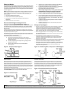
A. Dual Valve System
The system employs an ORI (open on rise of inlet pressure) valve and an ORD
( open on rise of dierential pressure) valve. The high pressure discharge gas
is introduced above the liquid in the receiver tank. The receiver discharge is
regulated by the ORI valve.
The discharge pressure of the ORI valve must be adjusted to regulate the unit
for proper operating conditions. Adjust the ORI valve shown on the following
diagram to maintain a discharge pressure of 160 to 180 PSIG.
A.
B.
C.
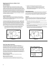
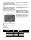
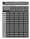
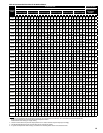
Table 1. Ambient Fan Cycle Thermostat Settings
Models
Design Thermostat Settings
T.D. T1 T2 T3
30 60
2-fan units: 25 65
20 70
4-fan units: 15 75
30 60 40
3-fan units: 25 65 55
20 70 60
6-fan units: 15 75 65
30 60 50 30
8-fan units: 25 65 55 40
20 70 65 50
15 75 70 60
NOTE: Cycle pairs of fans on double wide units.
Operation and Adjustment
Condensing units with dual valves require sucient charge to partially ood
the condenser during low ambient conditions.
Valve adjustment should be made with gauges connected to the discharge
port of the compressor. Adjustments should be made during mild or
low ambient conditions. Turning the valve stem “clockwise” on the ORI
valve will increase the discharge pressure, while turning the valve stem
“counterclockwise” will decrease the discharge pressure.
If adjustments are made during warm ambient conditions, it may not be
possible to adjust the regulator valve as low as desired. Readjustment may
be necessary once cooler conditions prevail.
B. Single Valve System
The standard valve used on high pressure refrigerant systems controls
the head pressure at approximately 180 PSIG. There is no adjustment for
this valve. On low pressure refrigerant systems the valve controls pressure
at approximately 100 PSIG. For energy eciency, the 100 PSIG valve is
sometimes used on high pressure refrigerant systems.
At condensing pressures above the valve setting, ow enters Port C and
leaves Port R. When the condensing pressure falls below the valve setting,
the valve modulates to permit discharge gas to enter Port D. Metering
discharge gas into the refrigerant ow leaving the condenser produces a
higher pressure at the condenser outlet, reduces the ow, and causes the
level of liquid refrigerant to rise in the condenser. This “ooding” of the
condenser with liquid refrigerant reduces the available condensing surface,
holding the condensing pressure at the valve setting.
C. Ambient Fan Cycle Control
This is an automatic winter control method which will maintain a condensing
pressure within reasonable limits by cycling fan motors in response to
outside air temperature. The thermostat(s) should be eld adjusted to shut
o the fan when the condensing temperature is reduced to approximately
90
˚
F. Table 1 lists approximate settings for several system T.D.’s. These settings
are approximate as they do not take into account variations in load.