


8
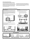
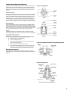
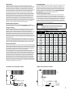
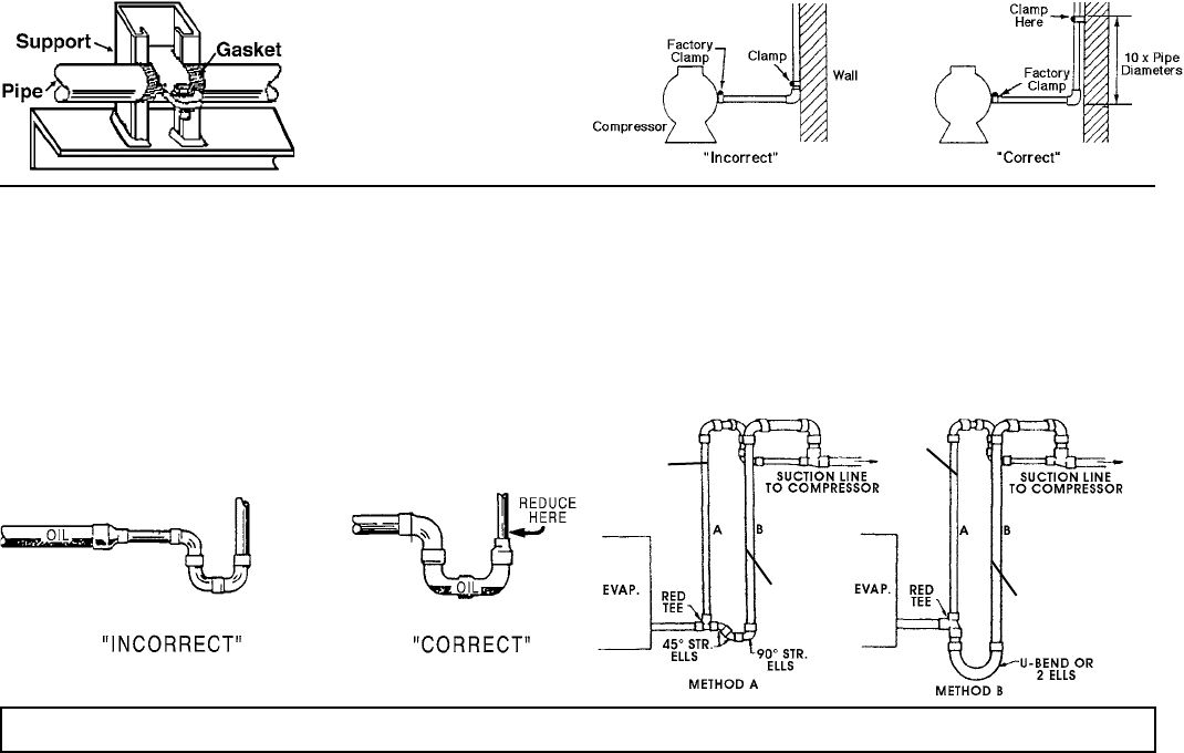
Figure 9. Example of Pipe Support Figure 10. Condensing Unit / Compressor to Wall Support
Suction Lines
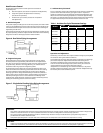
Horizontal suction lines should slope away from the evaporator toward
the compressor at the rate of 1/4 inch per 10 feet for good oil return. When
multiple evaporators are connected in series using a common suction line,
the branch suction lines must enter the top of the common suction line.
For dual or multiple evaporator systems, the branch lines to each evaporator
should be sized for the evaporator capacity. The main common line should
be sized for the total system capacity.
Suction lines that are outside of refrigerated space must be insulated. See
the Line Insulation section on page 14 for more information.
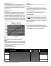
Phase Loss Monitor
The combination phase sequence and loss monitor relay protects the system
against phase loss (single phasing), phase reversal (improper sequence) and
low voltage (brownout). When phase sequence is correct and full line voltage
is present on all three phases, the relay is energized as the normal condition
indicator light glows.
Note: If compressor fails to operate and the normal condition indicator light
on the phase monitor does not glow, then the supplied electrical current
is not in phase with the monitor. This problem is easily corrected by the
following steps:
Turn power o at disconnect switch.
Swap any two of the three power input wires.
Turn power on. Indicator light should glow and compressor
should start.
Observe motors for correct rotation.
Recommended Refrigerant Piping Practices
The system as supplied by Heatcraft Refrigeration Products, was
thoroughly cleaned and dehydrated at the factory. Foreign matter may enter
the system by way of the evaporator to condensing unit piping. Therefore,
care must be used during installation of the piping to prevent entrance of
foreign matter.
Install all refrigeration system components in accordance with applicable
local and national codes and in conformance with good practice required for
the proper operation of the system.
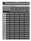
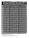
The refrigerant pipe size should be selected from the Line Sizing Tables. The
interconnecting pipe size is not necessarily the same size as the stub-out on
the condensing unit or the evaporator.
The following procedures should be followed:
Do not leave dehydrated compressors or lter-driers on
condensing units open to the atmosphere any longer than is
absolutely necessary.
Use only refrigeration grade copper tubing, properly sealed
against contamination.
Suction lines should slope 1/4" per 10 feet towards
the compressor.
1.
2.
3.
4.
a)
b)
c)
Suitable P-type oil traps should be located at the base of each
suction riser to enhance oil return to the compressor.
For desired method of superheat measurement, a pressure tap
should be installed in each evaporator suction line in
the proximity of the expansion valve bulb.
When brazing refrigerant lines, an inert gas should be passed
through the line at low pressure to prevent scaling and
oxidation inside the tubing. Dry nitrogen is preferred.
Use only a suitable silver solder alloy on suction and liquid lines.
Limit the soldering paste or ux to the minimum required to
prevent contamination of the solder joint internally. Flux only the
male portion of the connection, never the female. After brazing,
remove excess ux.
See Table 6 for discharge and liquid drain line sizes for remote
condenser connections.
If isolation valves are installed at the evaporator, full port ball
valves should be used.
Refrigerant Pipe Support
Normally, any straight run of tubing must be supported in at least two
locations near each end of the run. Long runs require additional
supports. The refrigerant lines should be supported and fastened
properly. As a guide, 3/8 to 7/8 should be supported every 5 feet; 1-1/8
and 1-3/8 every 7 feet; and 1-5/8 and 2-1/8 every 9 to 10 feet.
When changing directions in a run of tubing, no corner should be left
unsupported. Supports should be placed a maximum of 2 feet in each
direction from the corner.
Piping attached to a vibrating object (such as a compressor or
compressor base) must be supported in such a manner that will not
restrict the movement of the vibrating object. Rigid mounting will
fatigue the copper tubing.
Do not use short radius ells. Short radius elbows have points of excessive
stress concentration and are subject to breakage at these points.
Thoroughly inspect all piping after the equipment is in operation and
add supports wherever line vibration is signicantly greater than most
of the other piping. Extra supports are relatively inexpensive as
compared to refrigerant loss.
d)
e)
f)
g)
h)
i)
j)
1.
2.
3.
4.
5.
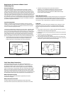
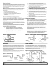
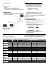
Figure 11. Suction P-Traps
Slope 1/4"
per 10 ft.
toward
compressor
Figure 12. Double Suction Riser Construction
Sized for
Minimum
Load
Sized
for Full
Load
Sized for
Minimum
Load
Sized
for Full
Load
Suction Line Risers
Prefabricated wrought copper traps are available, or a trap can be made
by using two street ells and one regular ell. The suction trap must be the
same size as the suction line. For long vertical risers, additional traps may
be necessary. Generally, one trap is recommended for each length of pipe
(approximately 20 feet) to insure proper oil movement. See Figure 11 for
methods of constructing proper suction line P-traps.
NOTE:
A suction line trap must be installed at the point where piping changes the direction of refrigerant ow from any horizontal run to an upward vertical run.