


23Heat & Glo • Supreme-N-I30AU, Supreme-P-I30AU • 2222-900 Rev. P • 6/12
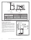
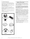
B. VentingComponents
CAUTION! Risk of Cuts/Abrasions/Flying Debris.
Wear protective gloves and safety glasses during instal-
lation. Sheet metal edges are sharp.
The vertical vent termination system installed on this model
includes:
• Flexible vent pipe for exhaust air (included with vent kit).
• One length of 3 in. (76 mm) flexible vent pipe for
combustion air (included with vent kit).
• One pipe-to-cap adaptor (included with vent kit).
• One vertical termination cap (included with vent kit).
8
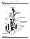
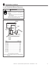
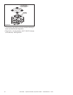
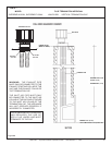
InstallingVentPipeandAppliance
Figure8.1
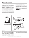
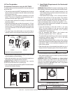
C. ConnectingVentPipe
Reference instructions in the termination kit.
• Install the 3-inch exible vent pipe(s) down through the
chimney.
• Secure the exhaust exible vent pipe to the exhaust
starting collar on to of the appliance with three screws
and seal with stove cement rated for continuous exposure
to 649 ºC (1200 ºF) or higher. See Figure 8.1.
• Use 3 screws to attach the section of inlet air vent to the
inlet collar on the collar slide plate and seal with stove
cement rated for continuous exposure to 649 ºC (1200
ºF) or higher. See Figure 8.1. NOTE: The collar slide
plate may be removed from appliance to aid installation.
See Figure 8.13 for horizontal venting with optional SLP
venting conguration.
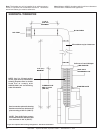
Vertical terminations are measured to top of chimney.
This appliance is listed for use with LINK-DV systems
and components only. It is permissible to extend venting
above existing chimney (within specied maximum verti-
cal limits) using SLP series or Duravent GS series 4 in. x
6-5/8 in. (101 mm x 168 mm) gas direct-vent pipe. The
link kit will need to be connected to the DV-46DVA-GK to
convert the LINK venting to SLP series. The vent must
be terminated with the cap supplied with the LINK-series
vent kit. Optional colinear to coaxial adapter may be used
to congure for SLP series piping. See Section 8.F.
WARNING! Risk of Fire/Explosion/Asphyxiation! Do
NOT connect this gas appliance to a chimney ue serving
a separate solid fuel or gas burning appliance.
• May impair safe operation of this appliance or other
appliances connected to the ue.
• Vent this appliance directly outside.
• Use separate vent system for this appliance.
CAUTION! ALL vent specications MUST be followed.
This product is tested and listed to these specications. Appli-
ance performance will suffer if specications are not followed.
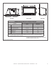
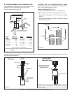
A. VentLimits
The abbreviations listed in this vent table key are used in
the vent diagrams.
Description
Minimum Vertical Run Length 13 ft. (4.0 m)
Maximum Vertical Run Length 40 ft. (12 m)
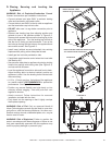
EXHAUST
AIR
VENT PIPE
TERMINATION
CAP
EXHAUST STARTING COLLAR
STARTING COLLAR BRACKET
EXHAUST STARTING COLLAR
INLET AIR STARTING COLLAR
STARTING COLLAR BRACKET
INLET AIR STARTING COLLAR
LOCKING TAB
INLET AIR
VENT PIPE
ADAPTER
V = 13 FT. (4.0 m) MINIMUM
40 FT. (12 m) MAXIMUM
NOTE: TO ACHIEVE OPTIMUM PERFOR-
MANCE OF INSERT, MINIMIZE OR AVOID
BENDS IN EXHAUST VENT PIPE.
EXHAUST
COLLAR
INLET
COLLAR
SEAL WITH STOVE CEMENT
1200º F (649ºC) OR HIGHER