


Heat & Glo • Supreme-N-I30AU, Supreme-P-I30AU • 2222-900 Rev. P • 6/1222
7
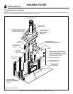
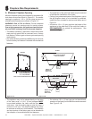
Installation Preparation
Prepare the existing solid fuel masonry or factory built
non-combustible rebox for installation.
A. InspectionandCleaning
Prior to installing the gas insert:
• Have the chimney and adjacent structure inspected
and cleaned by qualied professionals. Hearth & Home
Technologies recommends that NFI, CSIA or AS5601
certied professionals, or technicians under the direction
of certied professionals, conduct a minimum of a NFPA
211 Level 2 inspection of the chimney.
• Replace component parts of the chimney and replace
as specied by the professionals.
• Ensure all joints are properly engaged and the chimney
is properly secured.
• Ensure combustible mantel and surround clearances
comply with applicable codes and regulations for solid-
fuel replaces. In the absence of local or regional codes,
refer to NFPA 211 or AS5601.
• Ensure chimney is constructed of non-combustible
materials.
• Ensure chimney is clean and in good working order.
• Ensure that all chimney cleanouts t properly to prevent
air leakage into chimney.
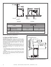
B. FlueDamper
Fully lock the solid fuel replace’s ue damper in the open
position, OR completely remove it.
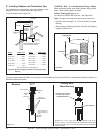
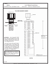
C. GasLine
Note: If the factory built replace has no gas access hole
provided, an access hole of 1 in. (25 mm) diameter or less
may be drilled through the lower sides or bottom of the
rebox in a proper workmanship - like manner. This access
hole must be plugged with non-combustible insulation after
the gas supply line has been installed.
• Install gas line into rebox cavity.
• Check local codes and gas line sizing requirements
AS5601. Australian Plumber’s Code applies.
• It is recommended that extra length of gas line be
installed within the existing wood burner or masonry
replace to allow removal of the insert for future servicing
needs.
An in-line regulator MUST be installed if the gas pressure
exceeds 3.4 kPa. Failure to install a regulator could dam-
age valve.
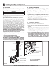
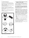
E. ElectricalOutletBox
An outlet box may be installed in a bottom back corner of
the existing solid fuel masonry or factory built replace to
power the appliance. Each unit ships standard with a cord
assembly to permit blowers or other optional accessories
to be used. The accessories plug may into the new outlet
box or be routed out onto the hearth to a nearby outlet.
D. FireplaceConversionNotice
Permanently attach the label with the following warning to
the inside lower back of the replace rebox into which the
insert is being installed. Silicone or mechanical fasteners
may be required to properly secure the label.
WARNING! Risk of Fire! This replace has been con-
verted for use with a gas replace insert only and cannot
be used for burning wood or solid fuels unless all original
parts have been replaced, and the replace re-approved
by the authority having jurisdiction.
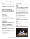
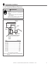
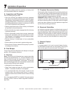
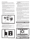
F. RemoteControl
IPI Models:
If a remote control kit is used to control blower function,
the AUX300CE module can only be placed in the control
cavity to the right of the control panel. See Figure 7.1.
Figure7.1LocationofAUX300CEforRemoteControlBlower
Function - IPI
AUX300CE MODULE