


25
A MAJOR CAUSE OF VENT RELATED FIRES IS FAIL-
URE TO MAINTAIN REQUIRED CLEARANCES (AIR
SPACES) TO COMBUSTIBLE MATERIALS. IT IS OF
THE UTMOST IMPORTANCE THAT DURACHIMNEY II
BE INSTALLED ONLY IN ACCORDANCE WITH THESE
INSTRUCTIONS.
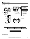
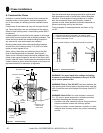
B. Clearances
Always allow at least a 2-inch clearance between Dura-
Chimney II Pipe and any combustible materials. Never fi ll
any required clearance space with insulation or any other
materials. Combustible materials include lumber, plywood,
sheetrock, plaster and lath, furniture, curtains, electrical
wiring, and building insulation.
C. Installation Notes
Proper planning for your DuraChimney II installation will
result in greater safety, effi ciency, and convenience, as well
as saving time and money. You must use only authorized
DuraChimney II parts to maintain a listed chimney system.
Do not mix parts or try to match with other products or use
improvised solutions. Do not install damaged or modi-
fi ed parts. Practice good workmanship. Sloppy work could
jeopardize your chimney’s safety. Keep electrical wiring
and building insulation away from all chimneys. When
deciding the location of your chimney, try to avoid modifi -
cations to roof beams and other structural components of
the building. If you have any questions, contact either your
dealer or Simpson Dura-Vent directly.
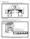
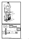
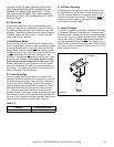
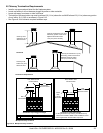
D. Frame Openings
From the ceiling, drop a plumb bob to the center of the
fi replace’s fl ue outlet and mark this center point on the ceil-
ing. Mark appropriate cutting lines around the center point.
Cut a square hole in the ceiling. Frame a level, square
opening centered over the hole that you have cut. Frame
openings at each fl oor level above the Fireplace (Figure
8.2). These openings are to hold the Firestop and Attic
Insulation shield. Locate each opening by dropping a plumb
bob to the four corners of the opening below. Maintain the
minimum 2-inch clearance/air space. Maintain the minimum
clearances and dimensions as specifi ed in Table 8.1.
Table 8.2
Diameter Framing Dimension
14” 21” X 21”
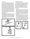
E. Cut Roof Opening
Determine and cut an opening in the roof directly above
the opening below, and at least 4-inches larger than the
chimney’s outside diameter to provide at least a 2-inch
clearance all around the chimney. The chimney must be
centered within this opening and maintain the minimum 2-
inch clearance to combustibles.
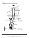
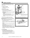
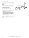
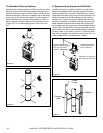
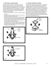
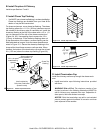
F. Install Firestop
A Firestop is required on each fl oor penetration in multisto-
ry installation. Building Codes require a Firestop at every
fl oor/ceiling level, including where the chimney penetrates
into the attic. Figure 8.2 shows a typical 2-story installation
with an attic. Note: a Firestop is not installed where the
chimney penetrates through the roof. The Firestop is in-
stalled on the underside of the ceiling/fl oor framing (Figure
8.3). Use a minimum of either (1) 8 penny nail or (1) 1-1/4”
wood screws per corner.
Framing
Figure 8.3
Heat & Glo • RUTHERFORD-50 • 4059-333 Rev C • 06/08