


24
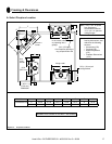
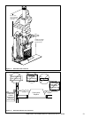
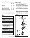
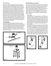
Termination
Cap
Storm
Collar
Chase Top
Flashing
Chase Top
Collar
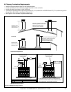
(4) Roof
Radiation
Shields
Chimney Section
Attic Insulation
Shield & Collar
Square Frame
Firestop
Chimney
Square Frame
Firestop
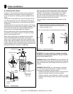
74 1/8 in.
(1883 mm)
Effective
Height
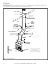
Figure 8.2
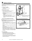
A. Chimney Requirements
Measure vertical distances from the base of the fi replace.
WARNING! Risk of Fire!
You must maintain 2 in. (51 mm)
air space clearance to insulation and other combustible
materials around the chimney system. Failure to do so may
cause overheating and fi re.
Feet Meters
• Minimum overall straight height 18 5.49
• Minimum height with offset/return 18.5 5.64
• Maximum height 50 15.24
• Maximum chimney length between an offset
and return
20 6.10
• Maximum distance between chimney
stabilizers
25 7.62
• Maximum unsupported chimney length
between the offset and return
6 1.83
• Maximum unsupported chimney height above
the fi replace
25 7.62
• Maximum unsupported chimney above roof 6 1.83
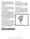
Height of Chimney Components in. mm
Stabilizer
14DCA-ST
Firestop
14DCA-FS
Roof Flashing
RF-1470
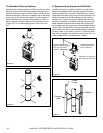
Elbows
14DCA-E15 - 15° Elbow
14DCA-E30 - 30° Elbow
Miscellaneous
14DCA-ES - Elbow Strap
14DCA-SS - Supplementary Support
14DCA-IS - Insulation Shield
14DCA-RRS - Roof Radiation Shield
14DCA-CTF - Chase Top Flashing
14DCA-VC - Chimney Cap
14DCA-SC - Storm Collar
14DCA-WS - Wall Strap
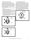
Chimney Sections*
14DCA-12 10 1/2 267
14DCA-18 16 1/2 419
14DCA-36 34 1/2 876
14DCA-48 46 1/2 1181
* Dimensions refl ect effective height.
Table 8.1
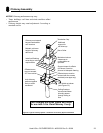
Determine the chimney components needed to complete
your particular installation:
• Measure the total vertical height of the fi replace installation
from the base of the fi replace assembly to the approximate
location of the bottom of the termination cap.
• Subtract the effective height of the fi replace assembly (see
Figure 8.2) from the total vertical height to determine the
overall height of the chimney installation.
• Create a schematic for your application similar to Figure
8.2 showing components required (referring to Table 8.1).
Figure 8.1 identifi es those components and where used.
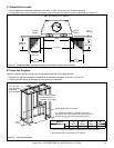
• Install a ceiling fi restop whenever the chimney penetrates
a fl oor/ceiling.
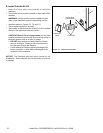
NOTICE: A maximum of one offset and return may be
used.
CAUTION! Risk of Fire and/or Asphyxiation! DO NOT
connect this fi replace to a chimney fl ue servicing another
appliance. Do NOT connect to any air distribution duct
or system. These actions could cause overheating/fi re
in the chimney fl ue, or release of exhaust fumes into the
living areas.
Heat & Glo • RUTHERFORD-50 • 4059-333 Rev C • 06/08