


57
Heat & Glo • SOHO-N-AUB • 2197-980 Rev. F • 5/12
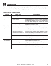
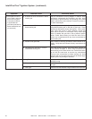
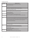
13
Finishing
A. Framing and Finishing Instructions
WARNING! Risk of Fire! Comply with all minimum clear-
ances to combustibles as specied. Framing closer than the
minimums listed must be constructed entirely of noncom-
bustible materials (i.e., steel studs, concrete board, etc.)
Finishing Instructions
It is important to follow the framing and nishing instruc-
tions to ensure proper placement of replace into the sur-
rounding framing/nishing materials.
Wall sheathing materials 3/8 in. (10 mm) thick are
specied in this installation manual to properly align with
the factory-installed non combustible material.
WARNING! Risk of Fire! DO NOT remove the factory-
installed non-combustible board or cover it with combus-
tible material, such as:
• Drywall (gypsum board)
• Plywood
• Materials that do not meet the ASTM E 136 Non-com-
bustibility standard (below).
Removal of factory-installed, non-combustible board and/
or use of materials not meeting the ASTM E 136 standard
may cause re.
Non-Combustible Materials Specication
Material which will not ignite and burn. Such materials are
those consisting entirely of steel, iron, brick, tile, concrete,
slate, glass or plasters, or any combination thereof.
Materials that are reported as passing ASTM E 136,
Standard Test Method for Behavior of Materials in a
Vertical Tube Furnace at 750 ºC and UL763 shall be
considered non-combustible materials.
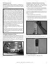
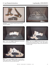
Setting the Fireplace into the Framing
Unlike many traditional, single-sided Heat & Glo replaces,
this replace is recessed into surround framing. The left
and right nailing tabs were designed so the replace is re-
cessed to the correct location within the framing materials.
1. Bend two nailing tabs away from replace 180 degrees
on both left and right nailing tabs. Do not adjust the
column standoffs. See Figure 13.1.
2. Screw each nailing tab to the adjoining framing material.
Ensure that the air space clearance is maintained on
the sides of the replace. See Figure 13.2.
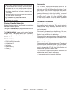
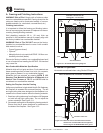
Figure 13.1 Noncombustible Facing Diagram
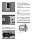
B. Mantel Projections
No mantels are allowed when using Studio-CE fronts.
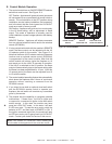
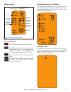
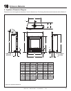
Figure 13.2 Minimum vertical and maximum horizontal
dimensions of combustibles above appliance
when using the DF-SOHOCE-BK dress guard.
Note: All dimensions are shown in millimeters
SEALANT MATERIAL
NON-COMBUSTIBLE ZONE
FINISH WALL MATERIAL MAY BE
COMBUSTIBLE - TOP AND SIDES
8 in.
203 mm
29 in.
740 mm
0 mm
0 mm
0 mm
127
178
102
OPENING OF FIREPLACE
76
127
203
305
51
229
254
279
152
26
407
152
178
203
229
254
279
305
330
356
381