


25
Heat & Glo • SOHO-N-AUB • 2197-980 Rev. F • 5/12
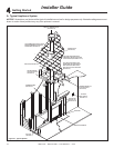
7
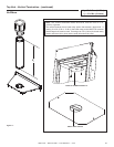
Vent Information and Diagrams
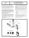
Figure 7.1
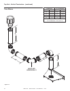
A. Approved Pipe
This appliance is approved for use with Hearth & Home
Technologies SLP venting systems. Refer to Section
16.C for vent component information.
DO NOT mix pipe, ttings or joining methods from differ-
ent manufacturers.
The pipe is tested to be run inside an enclosed wall.
There is no requirement for inspection openings at each
joint within the wall.
WARNING! Risk of Fire or Asphyxiation. This appli-
ance requires a separate vent. DO NOT vent to a pipe
serving a separate solid fuel burning appliance.
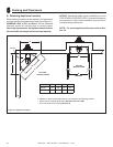
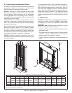
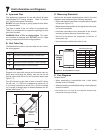
C. Use of Elbows
Diagonal runs have both vertical and horizontal vent as-
pects when calculating the effects. Use the rise for the
vertical aspect and the run for the horizontal aspect (see
Figure 7.1).
Two 45º elbows may be used in place of one 90º elbow.
On 45º runs, 1 ft. (305 mm) of diagonal is equal to 8-1/2
in. (216 mm) horizontal run and 8-1/2 in. (216 mm) vertical
run. A length of straight pipe is allowed between two 45º
elbows (see Figure 7.1).
B. Vent Table Key
The abbreviations listed in this vent table key are used in
the vent diagrams.
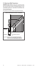
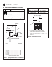
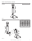
D. Measuring Standards
Vertical and horizontal measurements listed in the vent
diagrams were made using the following standards.
• Pipe measurements are shown using the effective length
of pipe (see Figure 7.2).
• Measurements are made from the appliance outer wrap,
not from the standoffs.
• Horizontal terminations are measured to the outside
mounting surface (ange of termination cap).
• Vertical terminations are measured to bottom of
termination cap.
• Horizontal pipe installed level with no rise.
Symbol Description
V
1
First section (closest to appliance) of vertical length
V
2
Second section of vertical length
H
1
First section (closest to appliance) of horizontal length
H
2
Subsequent sections of horizontal length
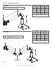
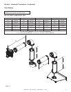
E. Flue Diagrams
General Rules:
• When penetrating a combustible wall, a wall shield
restop must be installed.
• When penetrating a combustible ceiling, a ceiling restop
must be installed.
• Horizontal runs of vent do not require vertical rise;
horizontal runs may be level.
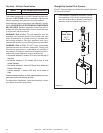
Figure 7.2 SLP Pipe Effective Length
Effective
Height/
Length
Horizontal
Vertical
8-1/2 in.
(216 mm)
8-1/2 in. (216 mm)
12 in.
(305 mm)
Effective Height/Length
Pipe inches mm
SLP4 4 102
SLP6 6 152
SLP12 12 305
SLP24 24 610
SLP36 36 914
SLP48 48 1219
SLP6A 2 - 6 51 - 152
SLP12A 2 - 12 51 - 305