


7
Heat Controller, Inc. HEV/H SERIES Installation, Operation & Maintenance
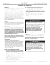
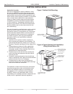
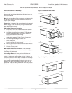
Notes:
1. While clear access to all removable panels is not required, installer should take care to comply with all building codes and allow
adequate clearance for future fi eld service.
2. Front & Side access is preferred for service access. However, all components may be serviced from the front access panel if side
access is not available.
3. Discharge fl ange is fi eld installed.
4. Condensate is 3/4” socket.
5. Source water and optional HWG connections are 1” swivel.
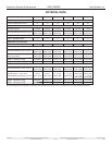
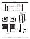
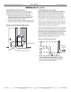
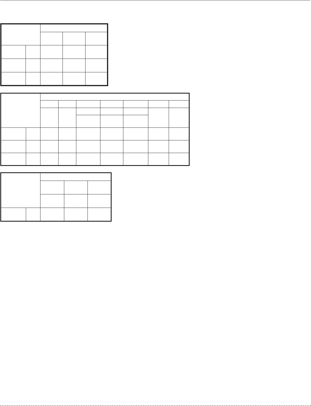
HE - VERTICAL UPFLOW DIMENSIONAL DATA
Vertical
Upfl ow
Model
Overall Cabinet
A
Width
B
Depth
C
Height
024-030
in
cm
22.4
56.9
22.4
56.9
40.5
102.9
036-042
in
cm
22.4
56.9
26.0
66.0
46.5
118.1
048 -060
in
cm
25.4
64.5
29.3
74.4
50.5
128.3
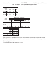
Vertical
Upfl ow
Model
Water Connections - Standard Units
12 3 4 5
D
Loop
In
E
Loop
Out
Cond. HWG In HWG Out
Loop
Water
FPT
HWG
FPT
FGH
024 - 030
in
cm
3.8
9.6
8.8
22.3
19.5
49.5
13.4
34.0
15.7
39.9
1
2.5
1
2.5
036 - 042
in
cm
3.8
9.6
8.8
22.3
22.1
56.1
15.2
38.6
18.5
47.0
1
2.5
1
2.5
048 - 060
in
cm
4.0
10.2
9.5
24.1
22.1
56.1
15.2
38.6
18.5
47.0
1
2.5
1
2.5
Vertical
Model
Electrical Knockouts
J
1/2”
K
1/2”
L
3/4”
Low
Voltage
Ext
Pump
Power
Supply
024 - 060
in
cm
4.6
11.7
6.1
15.5
7.6
19.3